A micro power network system

A micro-grid and micro-energy technology, applied in electrical components, circuit devices, AC network circuits, etc., can solve the problems of grid impact, impact, distributed power generation and distributed energy supply system promotion and application restrictions, etc., to weaken the impact and negative effects, the effect of reliable power supply

Inactive Publication Date: 2007-05-30
INST OF ELECTRICAL ENG CHINESE ACAD OF SCI
View PDF0 Cites 20 Cited by
  • Summary
  • Abstract
  • Description
  • Claims
  • Application Information

AI Technical Summary

Problems solved by technology

However, with the maturity and application of distributed power generation technology, the power operation department began to worry that the integration of a large number of distributed power generation devices at the edge of power system management into the power grid will cause a great impact and impact on the power grid. The promotion and application of power generation and distributed energy supply systems are greatly restricted

Method used


Image

  • A micro power network system
  • A micro power network system
  • A micro power network system

Examples


Embodiment Construction

[0021] The present invention is further described below with reference to the accompanying drawings and specific embodiments.

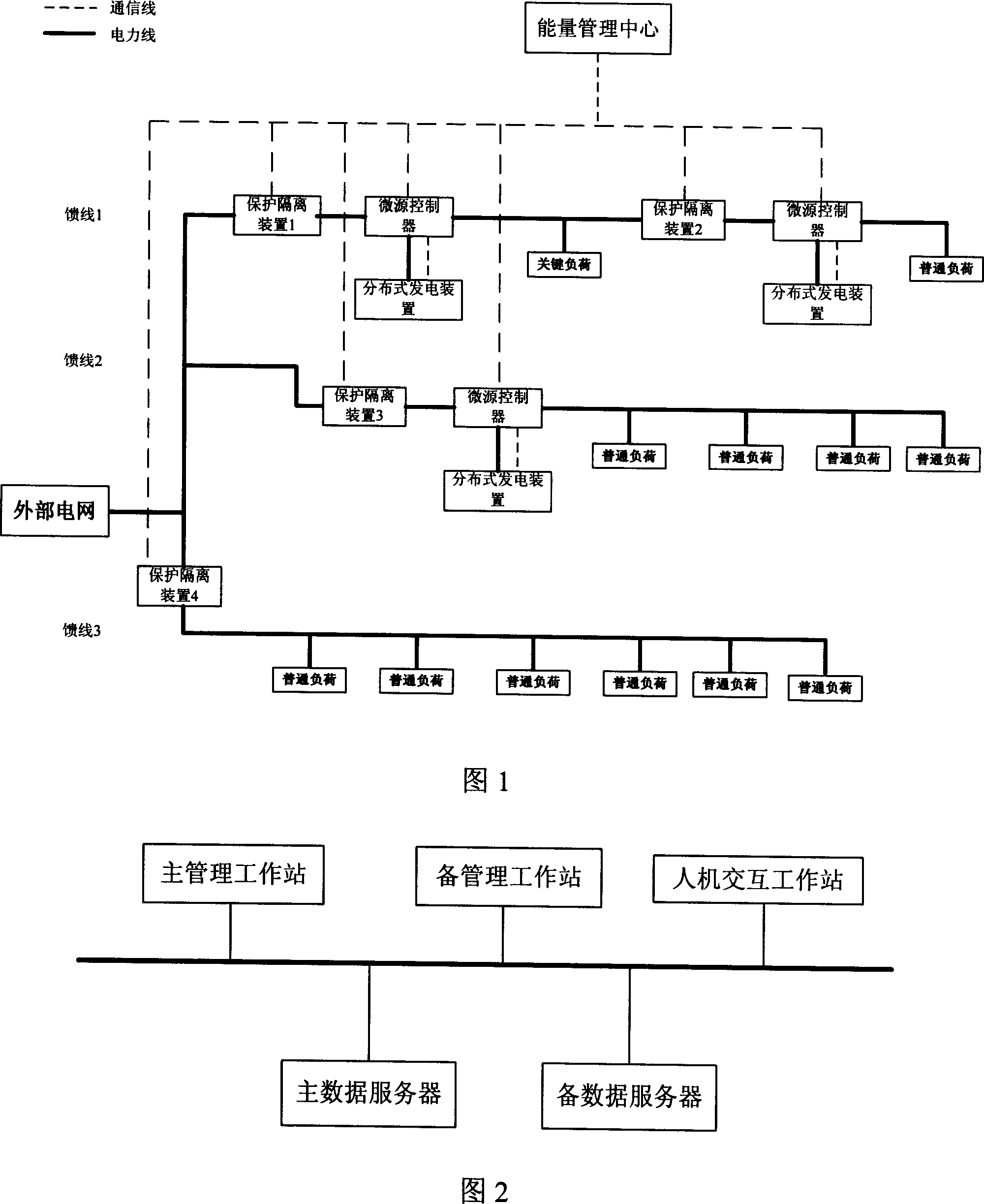
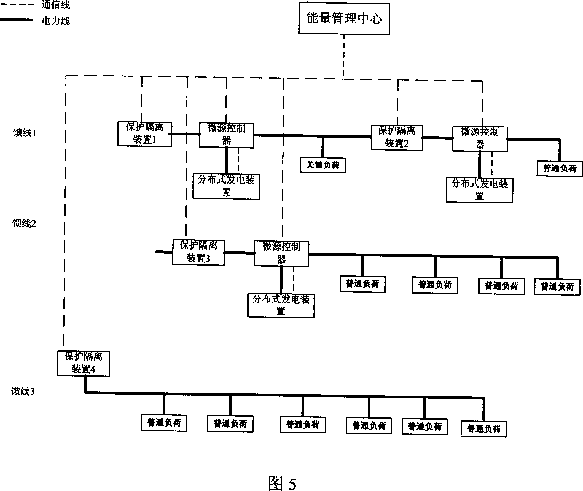
[0022] Figure 1 shows the overall composition and structure of the micro-grid. As shown in Figure 1, the present invention is composed of five parts: distributed power generation device, load, micro-energy controller, energy management center and protection isolation device, and it is a radial structure from left to right. The distributed generation device, the micro-energy controller, the load, and the protective isolation device are connected by cables (that is, the solid line shown in the figure) for energy transmission. The micro-energy controller and the protective isolation device interact with the energy management center, and receive instructions from the energy management center (ie, the dotted line shown in the figure). The protection isolation device is responsible for controlling the connection and disconnection of the energy transmission...


PUM


Abstract

This invention relates to one micro electricity network system, which comprises distribution power device, load and micro energy controller, energy management center and protection isolation device, wherein, the above parts are connected through cable; the micro energy controller and protection insulation device are interacting to receive energy management center order; the protection isolation device is in charge of distribution power device and load transmission channel and switch; each controller is for one distribution power device in charge of power flow and voltage.

Description

technical field [0001] The present invention relates to a microgrid system. Background technique [0002] The power system has developed into a large-scale interconnected network system with centralized power generation and long-distance power transmission, which can be continuously regulated by various controllers such as complex power flow, and is robust to most disturbances. However, in recent years, with the continuous increase of electricity load, users have more stringent requirements for safe, reliable and stable power supply, as well as the pressure on the power industry due to the environment and energy supply shortage, but the pace of power grid construction and development has not kept up with the requirements, making far The transmission capacity of distance transmission lines continues to increase, and the dependence of load-concentrated areas on external power continues to increase, which reduces the stability and security of power grid operation. The reasonab...

Claims


Application Information

Patent Timeline
Patent Type & Authority Applications(China)
IPC IPC(8): H02J3/00H02J3/38
Inventor 盛鹍许海平孔力齐智平裴玮
Owner INST OF ELECTRICAL ENG CHINESE ACAD OF SCI
Why Eureka
Try Eureka