Color correction method and color correction device

A technology for correcting matrix and color signals, applied to color TV, color TV components, color signal processing circuits, etc., can solve problems such as color cast emphasis

Inactive Publication Date: 2007-05-30
MITSUBISHI ELECTRIC CORP
View PDF2 Cites 8 Cited by
  • Summary
  • Abstract
  • Description
  • Claims
  • Application Information

AI Technical Summary

Problems solved by technology

Therefore, in the existing color correction method,

Method used


Image

  • Color correction method and color correction device
  • Color correction method and color correction device
  • Color correction method and color correction device

Examples


Embodiment Construction

[0023] Embodiment 1

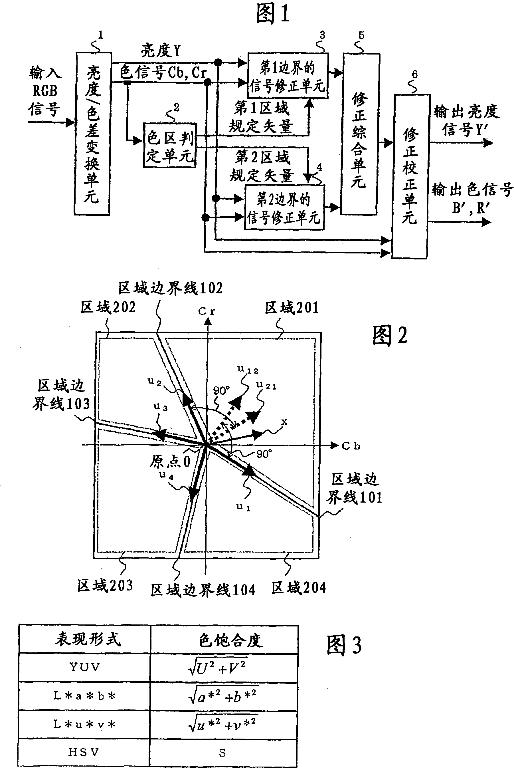
[0024] Fig. 1 is a block diagram showing a color correction device according to Embodiment 1 of the present invention. In FIG. 1 , the color correction device includes a brightness-color difference conversion unit 1 , a color zone determination unit 2 , a first boundary signal correction unit 3 , a second boundary signal correction unit 4 , a correction integration unit 5 , and a correction correction unit 6 . Among them, the color area judging unit 2 corresponds to a part constituting the color area judging device. The signal correction unit 3 of the first boundary, the signal correction unit 4 of the second boundary, and the correction integration unit 5 correspond to parts constituting the signal correction device. The operation will be described below.

[0025] The luminance / color difference conversion unit 1 converts the RGB signal obtained from the imaging element into any one of luminance and color signals of YCbCr, YUV, L*a*b*, L*u*v*, and HSV. ...


PUM


Abstract

In a color correction method of performing correction by dividing the color plane into a plurality of areas, and correcting the color according to different methods for each divided area, color shifts generated in converting color signal vectors are prevented from arising. When determining which area of the color signal plane divided by area boundary lines passing through the origin of the color signal plane includes the input color signal vector, and correcting the input color signal vector by converting the input color signal vector using a correction matrix having been designated in advance for the area determined to include the input color signal vector, a correction matrix including a component for performing parallel translation and a component for performing linear transformation is used as a correction matrix.

Description

technical field [0001] The present invention relates to the technique of correcting image color, in particular to a correcting method and its device for performing proper correction in each predetermined color zone. Background technique [0002] In imaging devices typified by digital cameras, single-plate CCDs are generally used. Color filters are placed on the entire surface of the CCD, and color images are obtained by interpolating colors. The spectral sensitivity characteristics of this color filter are different for each color, and since people have the characteristic of preferring vivid colors in memory to the green of trees or the blue of the sky rather than the actual colors, color correction is performed. Make it a favorite color (memory color). [0003] Generally, as such a color correction method, the color based on the RGB signal or the YCbCr signal of the image data is divided into regions, and each region is amplified with a preset gain, or a color correction ...

Claims


Application Information

Patent Timeline
IPC IPC(8): H04N9/64
CPCH04N9/68H04N9/646
Inventor 坂口隆明青木透的场成浩
Owner MITSUBISHI ELECTRIC CORP
Why Eureka
Try Eureka