Falling ball impact test machine

A technology of impact testing machine and falling ball, which is applied in the direction of testing the strength of materials, measuring devices, instruments, etc. by using one-time impact force. It can solve the problems of difficult control of height, cumbersome operation, and steel balls are easy to rebound and hurt people, so as to prevent human errors. Effect

Inactive Publication Date: 2007-06-06
重庆信威通信技术有限责任公司
View PDF1 Cites 17 Cited by
  • Summary
  • Abstract
  • Description
  • Claims
  • Application Information

AI Technical Summary

Problems solved by technology

[0003] Its disadvantages are: placing the steel ball manually is cumbersome to operate, and the height is not easy to control, and the steel ball is easy to rebound and hurt people after falling

Method used


Image

  • Falling ball impact test machine
  • Falling ball impact test machine
  • Falling ball impact test machine

Examples


Embodiment Construction

[0023] Below in conjunction with accompanying drawing and embodiment the present invention is further described:

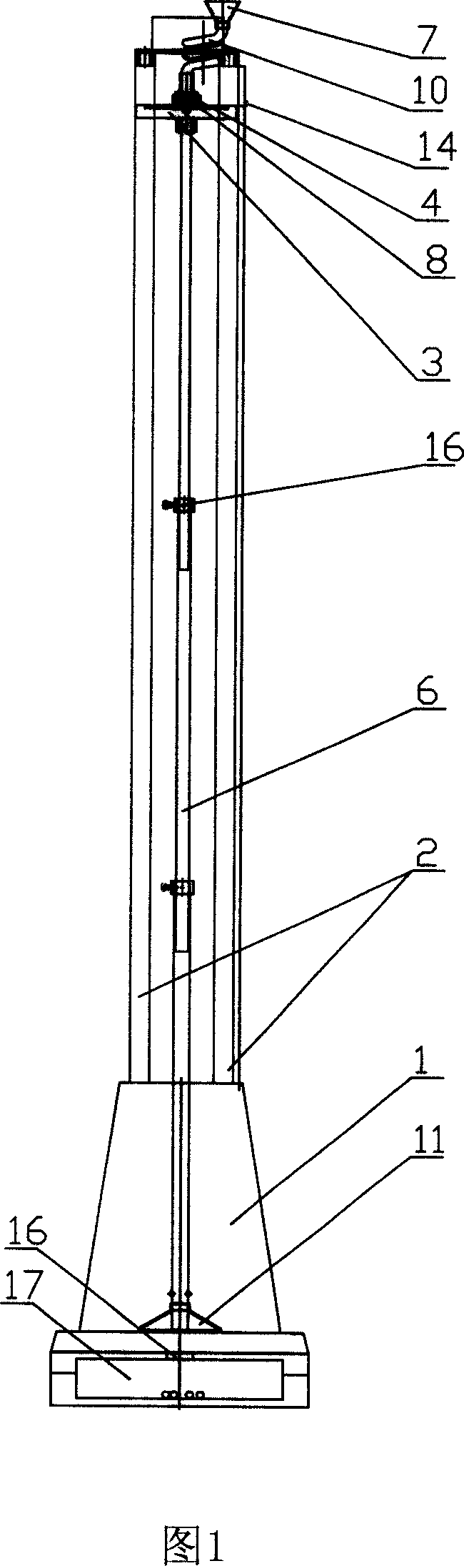
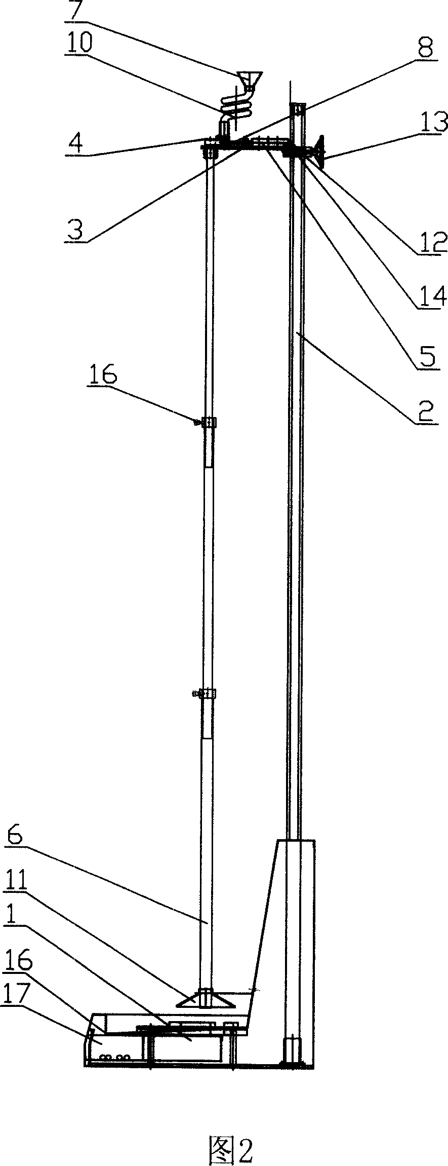
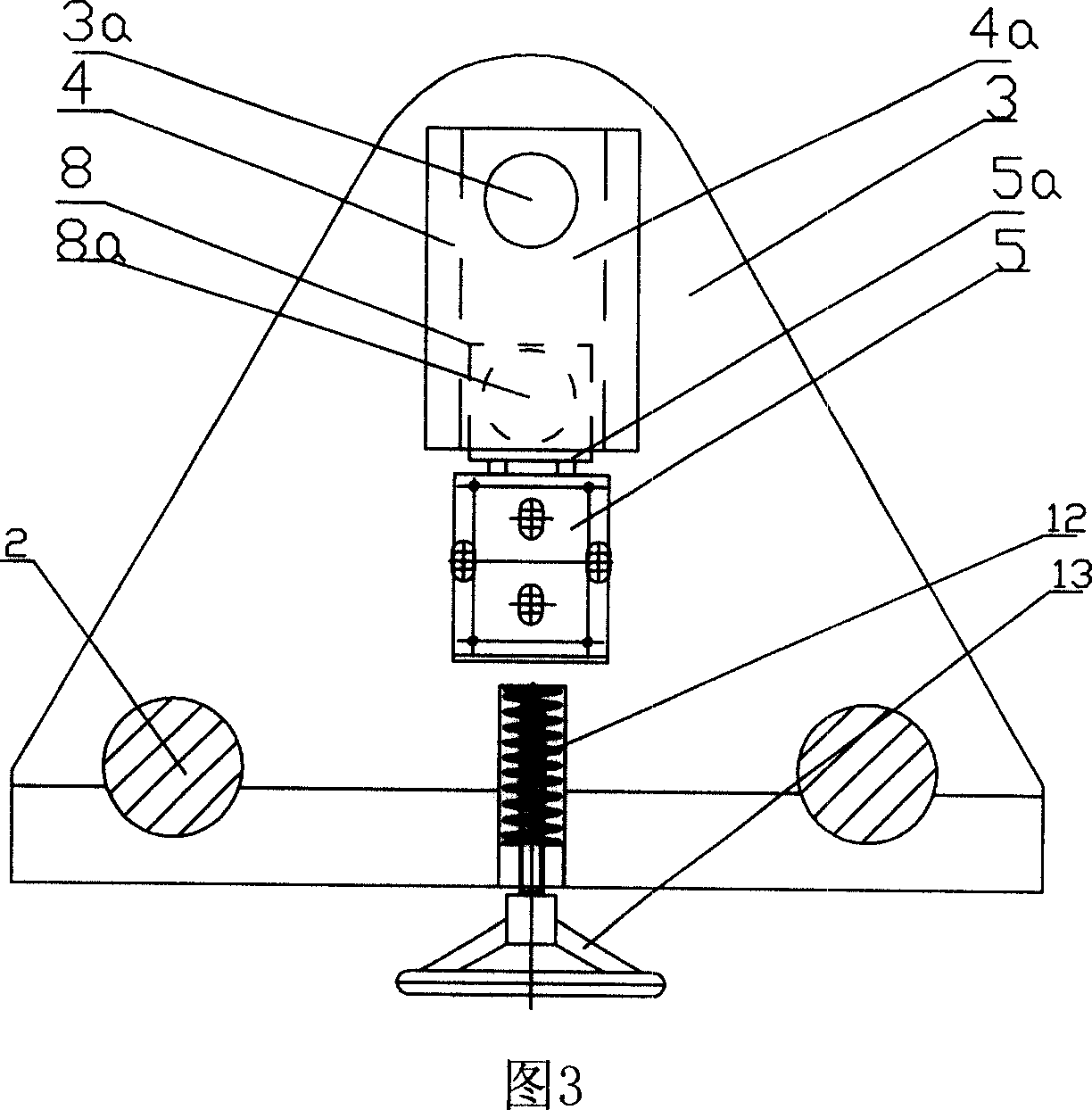
[0024] As shown in Fig. 1, Fig. 2, Fig. 3, Fig. 4 and Fig. 5: a falling ball impact testing machine includes a column 2 installed on the base 1, and a lifting platform 3 set on the column 2, the lifting platform 3 and column 2 are fixed by bolt 12, and the outer end of bolt 12 is fixed with handwheel 13;

[0025] As shown in Figure 3: the bolt 12 is covered with a spring to abut against the lifting platform 3, and the hand wheel 13 is turned to adjust the tightness between the lifting platform 3 and the column 2, so that the lifting platform 3 can slide up and down on the column 2.

[0026] Said lifting platform 3 is screwed with "冂" shaped block 4 and cylinder 5, wherein between "冂" shaped block 4 and lifting platform 3 forms rolling ball channel 4a; The ball window 4b is connected to the funnel 7; the lifting platform 3 at the other end of the rolling ball chan...


PUM


Abstract

This invention disclosed a testing machine for falling ball impulsion which consists of a column on the base and a platform on the column. The platform was fixed on the column by bolt; there is a grounder channel on the platform, one end connects to a filler and there is a bore on the other end; there are some pulling blocks in the channel. Complicated procedure of placing balls was replaced and the ball size and height were identical in this invention. It works efficiently and precisely.

Description

technical field [0001] The invention belongs to a device related to physical performance testing, in particular to a falling ball impact testing machine for testing impact resistance of products. Background technique [0002] The traditional falling ball impact testing machine, such as the impact testing machine of the patent No. 92219531.5, includes a column installed on the base, and a lifting platform set on the column, and a through hole is opened in the lifting platform, and the through hole is facing the clamping of the base. mechanism. When testing, the tested piece is fixed on the clamping mechanism, and the steel ball is manually lowered from the through hole of the lifting platform each time, so that the steel ball impacts the tested piece, and the impact effect is obtained. [0003] Its disadvantages are: placing the steel ball manually is cumbersome to operate, and the height is not easy to control, and the steel ball is easy to rebound and hurt people after fal...

Claims


Application Information

Patent Timeline
IPC IPC(8): G01N3/303G01N3/30
Inventor 蒋龙李剑雄陈绪贵王技平
Owner 重庆信威通信技术有限责任公司
Why Eureka
Try Eureka