
Electric oven

一种电烤箱、箱门的技术,应用在电烤箱领域,能够解决烫伤、降低箱门冷却效率等问题,达到加工简洁、高质量外观、提高冷却效率的效果

Inactive Publication Date: 2007-06-13
LG ELECTRONICS INC
View PDF0 Cites 2 Cited by
  • Summary
  • Abstract
  • Description
  • Claims
  • Application Information

AI Technical Summary

Problems solved by technology

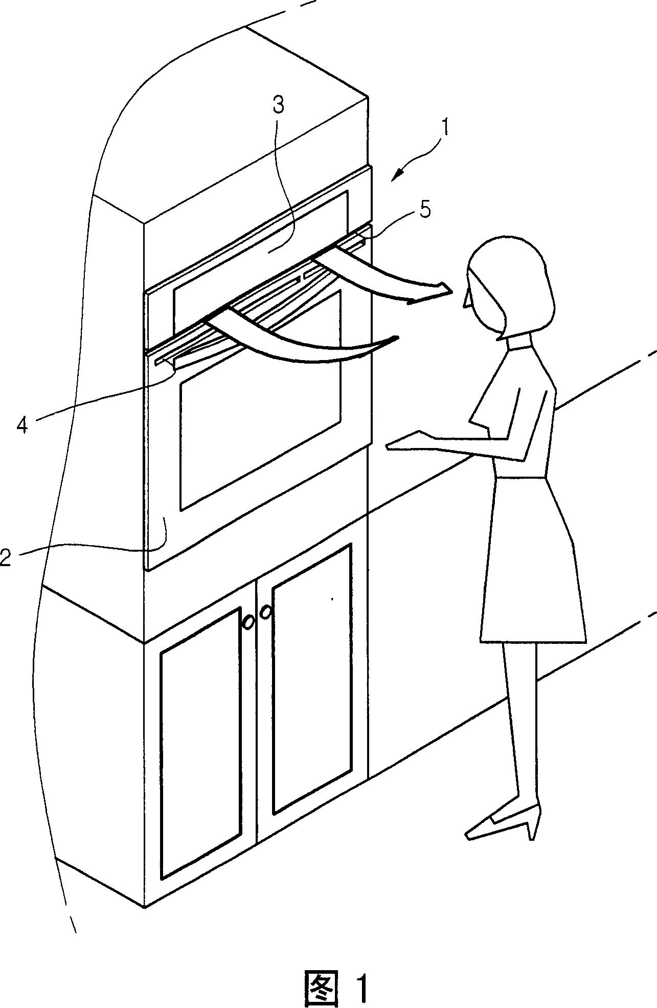
Therefore, if a user stands close to the front side of the electric oven 1, he or she may be scalded by the high-temperature air discharged from the exhaust hole 5
[0008] In addition, since the suction hole 4 and the exhaust hole 5 are formed close to each other, the discharged high-temperature air is sucked again through the suction hole 4, thereby reducing the cooling efficiency of the box door.
[0009] Also, when the air suction hole 4 is formed at the lower end of the door 2, the air introduced into the door rises to cool the door, which reduces the cooling efficiency of the door.

Method used


Image

  • Electric oven
  • Electric oven
  • Electric oven

Examples


Embodiment Construction

[0026] Reference will now be made in detail to the preferred embodiments of the invention, examples of which are illustrated in the accompanying drawings. Wherever possible, the same reference numbers will be used throughout the drawings to refer to the same or like parts.

[0027] An embodiment of a built-in electric oven will be described below according to a solution of the present invention.

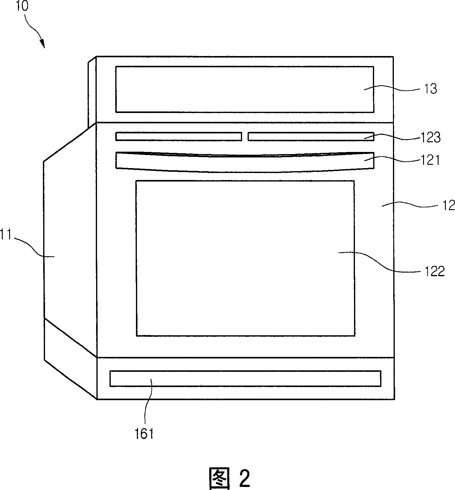
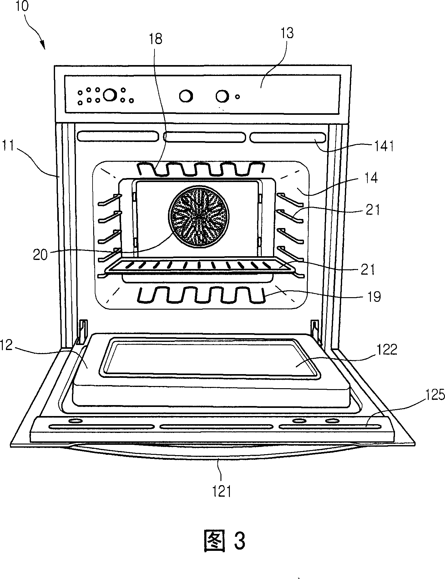
[0028] Fig. 2 is an external perspective view of an electric oven according to a solution of the present invention, and Fig. 3 is a perspective view of an internal structure of an electric oven according to a solution of the present invention.

[0029] With reference to Fig. 2 and Fig. 3, electric oven 10 according to the present invention comprises: casing 11; Cavity 14, it is protected by this casing 11, and has cooking chamber (cooking chamber) in this cavity 14; Cabinet door 12, It is rotatably arranged on the front side of the cavity 14; the control panel 13 is installed on the...


PUM


Abstract

An electric oven includes a cavity, a door rotatably installed at a front surface and including an air suction hole formed at one side of the outside thereof and an air discharge hole formed at one side of the inside thereof; and an air suction / discharge member mounted outside the cavity and allowing the indoor air to be sucked through the air suction hole and to be discharged to a lower side of the cavity.

Description

technical field [0001] The invention relates to an electric oven, in particular to a door cooling structure of the electric oven. The door cooling structure can prevent the high-temperature air generated when the oven is driven from being discharged to the user's face, and can improve the cooling channel of the oven door. And improve the cooling performance of the door. Background technique [0002] In general, an electric oven is a cooking device that cooks food using heat generated by a heating member such as a heater provided in a cavity. Electric ovens are divided into vertical electric ovens and built-in electric ovens. Specifically, the vertical electric oven is independently installed at a location like the radiator, while the built-in electric oven is installed so that its cavity is partially embedded in the wall of the kitchen. [0003] Fig. 1 is a front view of a built-in electric oven in the prior art. [0004] Referring to FIG. 1 , a prior art built-in electri...

Claims


Application Information

Patent Timeline
Patent Type & Authority Applications(China)
IPC IPC(8): F24C7/04
CPCF24C15/006F24C15/04F24C15/025F24C7/046
Inventor 李映佑金完洙李容守赵晟浩
Owner LG ELECTRONICS INC
Learn More