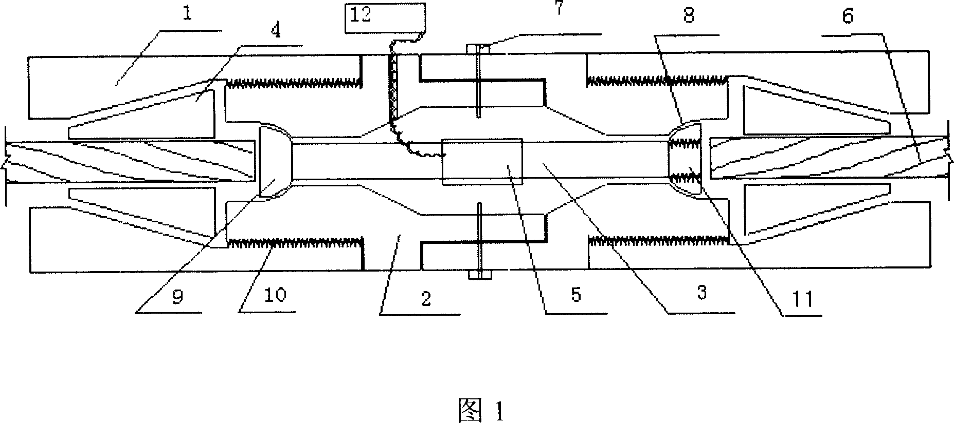
Steel twisted-line tension-force measuring device
A technology of tension measurement and steel strand, which is applied in the field of steel strand tension measurement in the anchorage section of the anchor cable, which can solve the problems of construction difficulties, loose strain gauges and stress, high material requirements for force measuring devices, etc., and achieve the force mode Intuitive and simple, avoid damage, accurate tension effect
Inactive Publication Date: 2007-06-13
SOUTH CHINA UNIV OF TECH
View PDF0 Cites 9 Cited by
- Summary
- Abstract
- Description
- Claims
- Application Information
AI Technical Summary
Problems solved by technology
The disadvantages of this approach are: first, it causes a certain degree of damage to the structure of the raw material; second, the most important aspect is that each bundle of steel strands is formed by intertwining multiple steel wires (for example, seven Ф5 steel wires are wound After forming a 15.24 steel strand), the outer surface is extremely irregular, and the deformation of each steel wire is inconsistent when the steel strand is pulled, so it is easy to cause the strain gauge to be loose and damaged and the force is uneven, which seriously affects the test accuracy
Method used
View moreImage
Smart ImageViewing Examples
Examples
 PUM
 Abstract
The invention relates to a steel strand jacking force measuring device that includes strain meter, two inner sleeves, two outer sleeves and round steel. The two inner sleeves movably connect, and has round hole in center. The round steel is locating in the hole. Two ends of round steel have protuberance, whose diameter is larger than that of the hole. Strain gauge is stuck on round steel. The wire connects to strain gauge through the hole on inner sleeve. And the two ends of inner sleeve connect to the two ends of outer sleeve. Hole used for passing through steel strand is set in the center of sleeve. Cone cavity is set at the back of hole. And cutting off the steel stand, it could be connected to the cone clamping piece in cavity. The strain gage and steel strand is on the same axis. The invention has high accuracy, safety and reliability. It could realize monitoring the whole process of the pulling and using of the steel strand.
Description
technical field [0001] The invention relates to the measurement of the tensile force of steel strands in the anchoring section of the anchor cable, and the device can be widely used in engineering fields using prestressed steel strands for anchoring, such as bridges, water conservancy, slope protection, and buildings. Background technique [0002] The prestressing project is a complex concealed project, coupled with the constraints of inevitable factors such as pipe bending and steel strand twisting during the construction process, in order to test the tension of a single steel strand and its anchorage The distribution situation poses great difficulties. At present, the main method used: one method is to directly paste the strain gauge on the steel strand. The disadvantages of this approach are: first, it causes a certain degree of damage to the structure of the raw material; second, the most important aspect is that each bundle of steel strands is formed by intertwining mu...
Claims
Login to View More Application Information
Patent Timeline
 IPC IPC(8): G01L5/04G01L5/10
Inventor 周希平
Owner SOUTH CHINA UNIV OF TECH
Features
- R&D
- Intellectual Property
- Life Sciences
- Materials
- Tech Scout
- Unparalleled Data Quality
- Higher Quality Content
- 60% Fewer Hallucinations
Learn More Browse by: Latest US Patents, China's latest patents, Technical Efficacy Thesaurus, Application Domain, Technology Topic, Popular Technical Reports.
© 2025 PatSnap. All rights reserved.Legal|Privacy policy|Modern Slavery Act Transparency Statement|Sitemap|About US| Contact US: help@patsnap.com

