Automatic pressure relief type grouting anchor rod

A technology of grouting bolts and automatic venting, which is applied in the installation of bolts, mining equipment, earthwork drilling and mining, etc. It can solve the problems of time-consuming and laborious anchoring construction, affecting the effect of grouting, and clogging of grouting holes, etc., and achieves labor reduction. Strength, the effect of improving anchorage efficiency

Active Publication Date: 2019-10-15
古小辉
View PDF6 Cites 1 Cited by
  • Summary
  • Abstract
  • Description
  • Claims
  • Application Information

AI Technical Summary

Problems solved by technology

[0004] However, when the above-mentioned automatic pressure relief type grouting anchor is in use, it must be divided into two stages: initial anchoring and grouting anchoring, and the former must be completed by manual operation of the anchor body and casing. On the working surface, the labor intensity of the staff will increase sharply, resulting in time-consuming and labor-intensive problems in anchoring construction
[0005] In addition, because the grouting hole is always exposed, during the construction process, the dust left in the drilling will enter the grouting hole, resulting in blockage of the grouting hole and affecting the effect of post-grouting

Method used


Image

  • Automatic pressure relief type grouting anchor rod
  • Automatic pressure relief type grouting anchor rod
  • Automatic pressure relief type grouting anchor rod

Examples


Embodiment Construction

[0022] In order to make the technical purpose, technical solution and beneficial effect of the present invention clearer, the technical solution of the present invention will be further described below in conjunction with the drawings and specific embodiments.

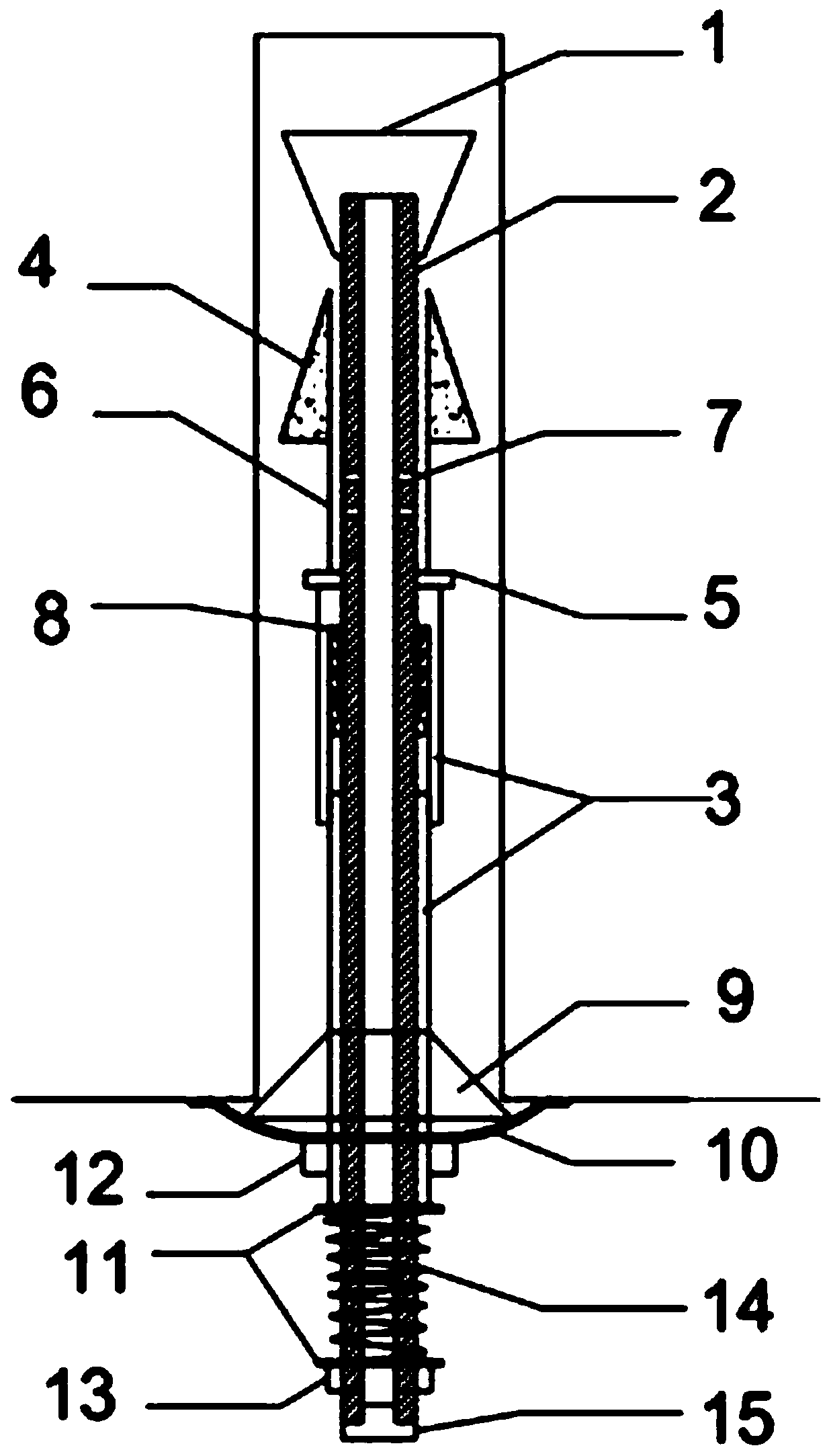
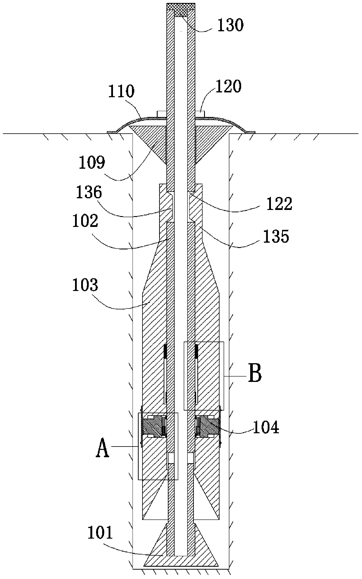
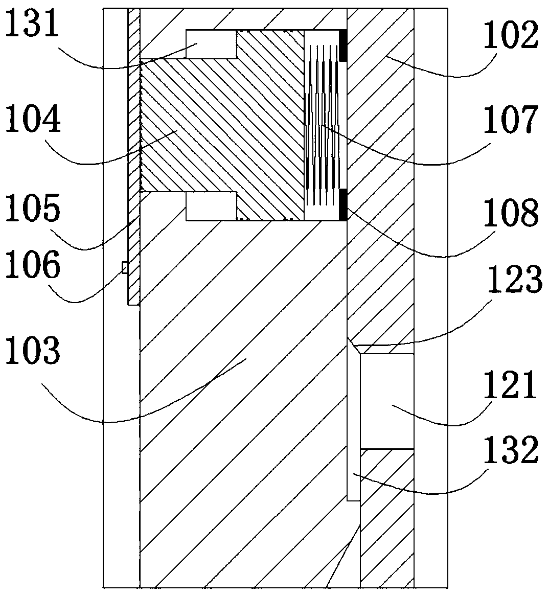
[0023] see figure 1 , shows the structure of the automatic pressure relief grouting anchor in this embodiment, which mainly consists of the anchor head 101, the anchor body 102, the anchor sliding sleeve 103, the anchor slider 104, the breakable block 105, Screw 106, spring 107, spring retaining ring 108, grout stopper 109, backing plate 110, lock nut 120 and grout plug 130 constitute. The anchor head 101 is fixed on the front end of the anchor body 102, the anchor sliding sleeve 103 is slidably and tightly sleeved on the anchor body 102, and the anchor sliding sleeve 103 is arranged behind the anchor head 101 at intervals, and the anchor sliding block 104, Broken baffles 105, screws 106, springs 107 and spring retain...


PUM


Abstract

The invention relates to an automatic pressure relief type grouting anchor rod. Anchoring slide sleeves which are arranged behind an anchor rod head in a spaced mode sleeve outside an anchor rod bodyin a sliding sealing mode; anchoring through holes are formed in the inner walls of the anchoring slide sleeves; anchoring slide blocks which are in sliding fit to the hole walls of the anchoring through holes are formed in the anchoring through holes in a sliding mode; outer-end orifices of the anchoring through holes are equipped with pulverizable blocking sheets in a blocking mode; a table shoulder which faces towards and is in sealing fit to the slot bottom of a ring slot is arranged at the periphery of the anchor rod body in a sealing mode; a ring-shaped interval space is formed between the step surface of the table shoulder and the front side slot wall of the ring slot; a radial through hole which communicates with the ring-shaped interval space is formed in the anchor rod body; thetops of the anchoring slide sleeves are equipped with elastic claws capable of being elastically shrunk and stretched; step-shaped locking blocks which are bulged on the inner walls are arranged on the rear parts of the elastic claws; and the step-shaped locking blocks are embedded into grouting long holes formed in the top of the anchor rod body. The automatic pressure relief type grouting anchorrod cancels the original step of regulating an anchorage state of the anchor rod, so that labor intensity of a worker in a construction process is reduced, and anchoring efficiency is improved.

Description

technical field [0001] The invention relates to a bolt, in particular to an automatic pressure relief grouting bolt, which is mainly used in the technical field of geotechnical engineering. Background technique [0002] With the increasing mining depth of global mineral resources, various engineering geological disasters are increasing, such as mine rock burst and large deformation of soft rock, which pose a huge threat to the safe and efficient mining of deep resources. The roadway supported by traditional bolts is far from being able to resist the instantaneous large deformation impact load caused by rockburst, resulting in accidents of bolt breakage and roadway damage. At present, in the support of underground engineering, the weak roadway roof is usually suspended in the upper stable rock formation by means of bolts, and resin anchoring agents are mostly used for anchoring the ends of bolts in engineering, but with the increase of the service life of the roadway, anchori...

Claims


Application Information

Patent Timeline
Patent Type & Authority Applications(China)
IPC IPC(8): E21D21/00E21D20/02
CPCE21D20/021E21D21/0026
Inventor 古小辉周峰张锦杨警卫岳昌旭张力张世雷彭见闵超张晓磊孟涛
Owner 古小辉
Why Eureka
Try Eureka