

Device for moulding chopped preparations
A forming device and mincing technology, which can be used in meat extrusion, slaughtering, household appliances, etc., can solve the problems of complex and expensive implementation of automatic stop equipment
- Summary
- Abstract
- Description
- Claims
- Application Information
AI Technical Summary
Problems solved by technology
Method used
Image

Examples
no. 3 example Embodiment
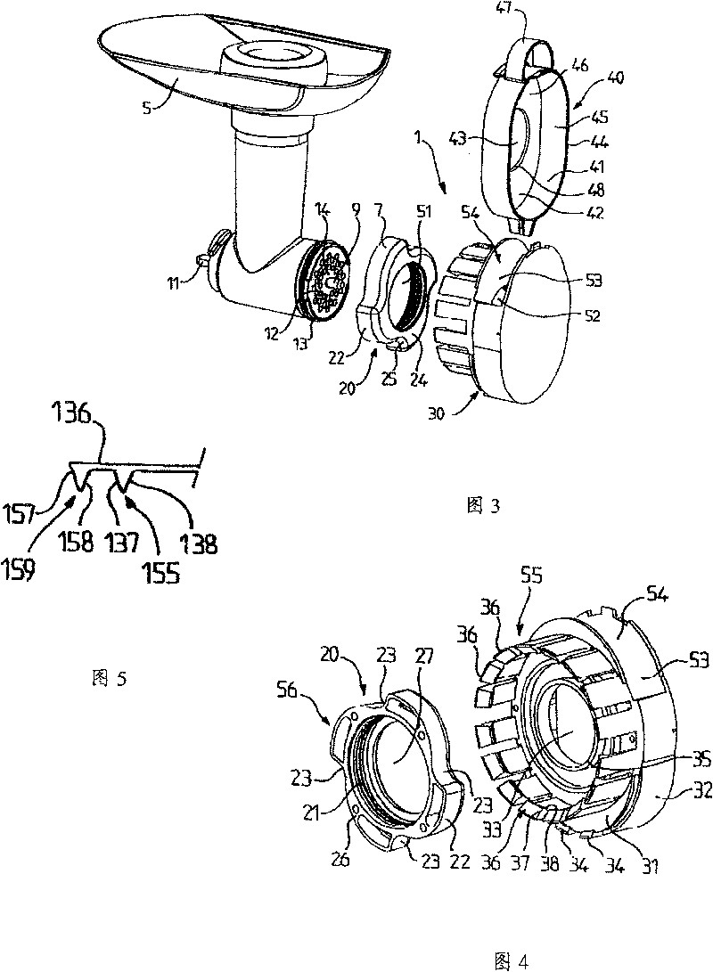
[0098] The user installs the cutter 2" with the nut on the mincer motor and then installs the mounting part 21" of the support 20" on the nut 7". The user then assembles the shell assembly 30" with the support 20" by placing the support wall 33" on the rod 70". The user places the ground article forming attachment 40"on the front wall panel 31"of the housing assembly 30"by using, for example, the gripping device 47". To this end, the user can apply pressure to the peripheral wall 41 ″ to deform the central elastic hinge 60 ″ so that the outer transverse ribs 63 ″, 64 ″ can abut against it inside the side wall 32 ″. The chamber 53 ″ is supported by the support 20 "And shell assembly 30 " form, and it has an introduction port that places crushed product forming attachment 40 ". Compared with the situation in the original state, the end edge 48 of the peripheral wall panel 41 " placed in the chamber 53 " ″, 49″ close to each other. If desired, the peripheral wall 41″ can also be...
PUM
 Abstract
Description
Claims
Application Information