
Micro-optic reflecting component

A technology of optical reflection and components, applied in the direction of optical components, optics, installation, etc.

Active Publication Date: 2012-11-14
FRAUNHOFER GESELLSCHAFT ZUR FOERDERUNG DER ANGEWANDTEN FORSCHUNG EV
View PDF2 Cites 0 Cited by
  • Summary
  • Abstract
  • Description
  • Claims
  • Application Information

AI Technical Summary

Problems solved by technology

The disadvantage of both methods is that a very high voltage is required to deform the diaphragm

Method used


Image

  • Micro-optic reflecting component
  • Micro-optic reflecting component
  • Micro-optic reflecting component

Examples


Embodiment Construction

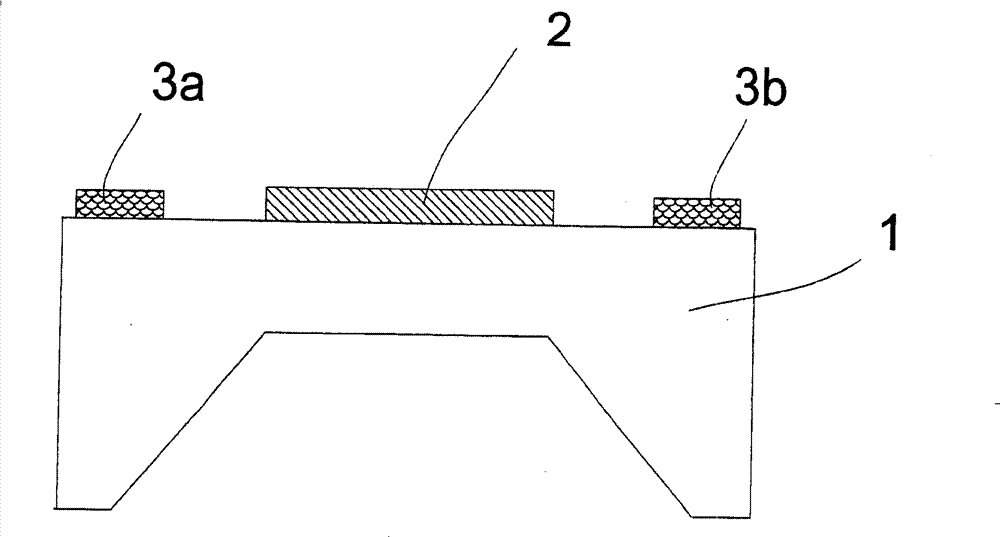
[0036] figure 1 A cross-section of a component fabricated using microsystems techniques is given. A substrate 1 consisting of silicon is machined from the back as a diaphragm. Bimorph properties can be achieved by the deposition of a reflective layer 2 . The contact points 3a, 3b are arranged on both sides. When a voltage is applied between these contact points 3a, 3b, current flows through the substrate 1 via the contact points and heats the membrane. The curvature of the membrane is changed by the resulting temperature increase.

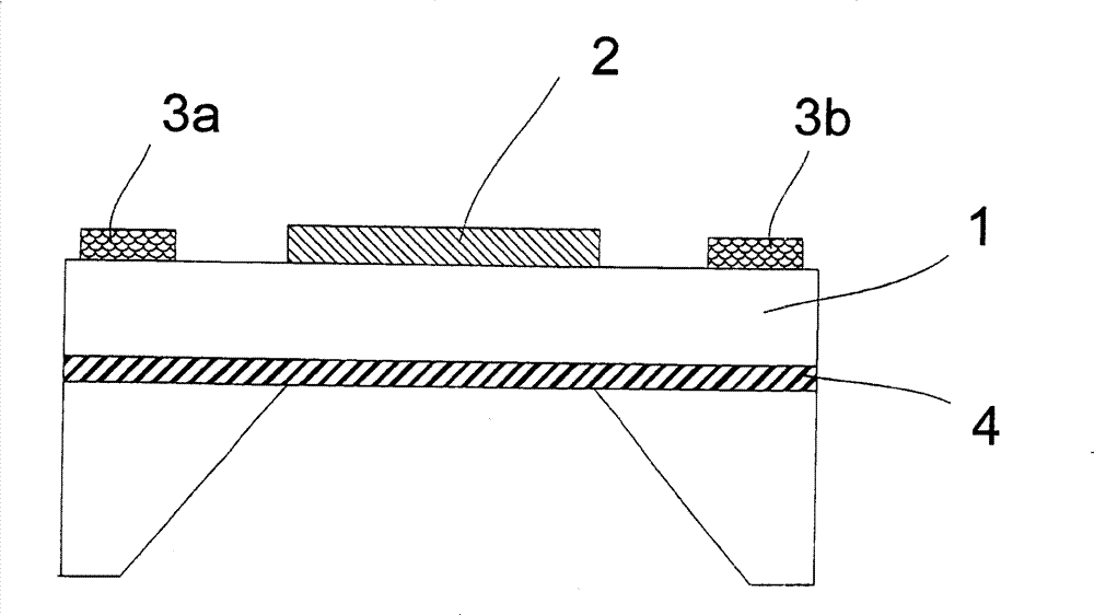
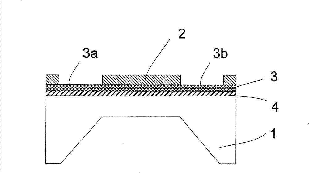
[0037] figure 2 A similar principle is given, but here the substrates 1 are separated by an electrically and thermally insulating intermediate layer 4 . This intermediate layer 4 serves on the one hand as an corrosion stop during the production of the component and on the other hand thereby reduces the heat conduction from the diaphragm to the separated substrate regions. Furthermore, the application of a third layer - in addition to substr...


PUM


Abstract

The invention relates to active microoptic reflecting components for adapting or changing the focal length or focal position in optical systems. It is the object of the invention to make available a miniaturised reflecting microoptic component for focusing or defocusing incident electromagnetic radiation, with which a variation in the focal distance can be achieved simply and at low cost. On the component according to the invention there is an elastically deformably membrane which is formed at least with one reflecting layer comprising a first material or material mixture and at least with one further layer or substrate which is formed from a second material or material mixture. First and second materials or material mixtures have thermal coefficients of expansion which deviate from each other. In addition a heating or temperature control mechanism is present.

Description

technical field [0001] The present invention relates to active micro-optic reflective assemblies for matching or changing the focal length and focus position in an optical system. Background technique [0002] When optically detecting measured variables or data, the position of the focal point has to be changed in many cases and the lack of the ability to change will limit the performance of the measurement / detection system. For example in the following confocal measurement principle, where a change in focus position is utilized and barcodes are read with a laser scanner, the absence of focus change would lead to a limited performance. [0003] a) Measurement system based on focus position change: This confocal measurement principle is mainly used to measure the surface topology (topology) structure of an object. For this, the focus must be changed perpendicular to the surface (z-direction). This is usually achieved in such a way that the optical path length from the point...

Claims


Application Information

Patent Timeline
Patent Type & Authority Patents(China)
IPC IPC(8): G02B7/28
CPCG02B26/0866G02B26/0825
Inventor 蒂洛·桑德纳沃尔弗拉姆·普夫哈拉尔德·希恩克
Owner FRAUNHOFER GESELLSCHAFT ZUR FOERDERUNG DER ANGEWANDTEN FORSCHUNG EV
Learn More