AI technical title is built by Patsnap AI team. It summarizes the technical point description of the patent document.
A vise and fixture technology, applied in the field of improved quick clamping methods and devices, capable of solving problems such as limitations
Inactive Publication Date: 2007-06-20
THE CLAMP
View PDF18 Cites 13 Cited by
Summary
Abstract
Description
Claims
Application Information
AI Technical Summary
This helps you quickly interpret patents by identifying the three key elements:
Problems solved by technology
Method used
Benefits of technology
Problems solved by technology
As indicated in this patent disclosure, this teaching is limited to jaw positioning by tooth engagement.
[0005] [5] These prior art patents have several disadvantages, including the available system adjustment and control of the blocks relative to each other in these systems and the overall strength of the system provided by their method of connection
Method used
Image
Click on the blue label to locate the original text in one second.
Reading with bidirectional positioning of images and text.
Examples
Embodiment Construction
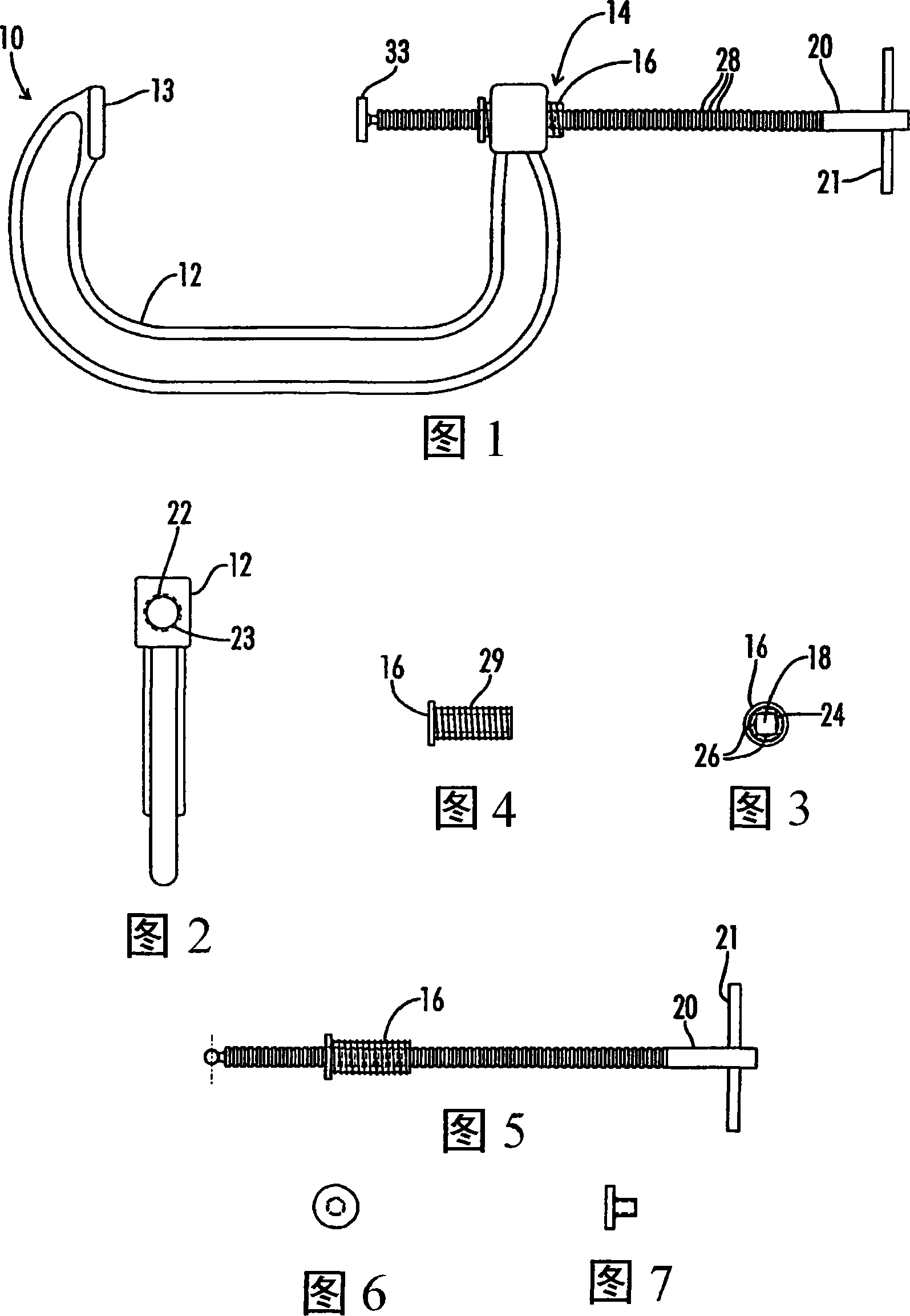
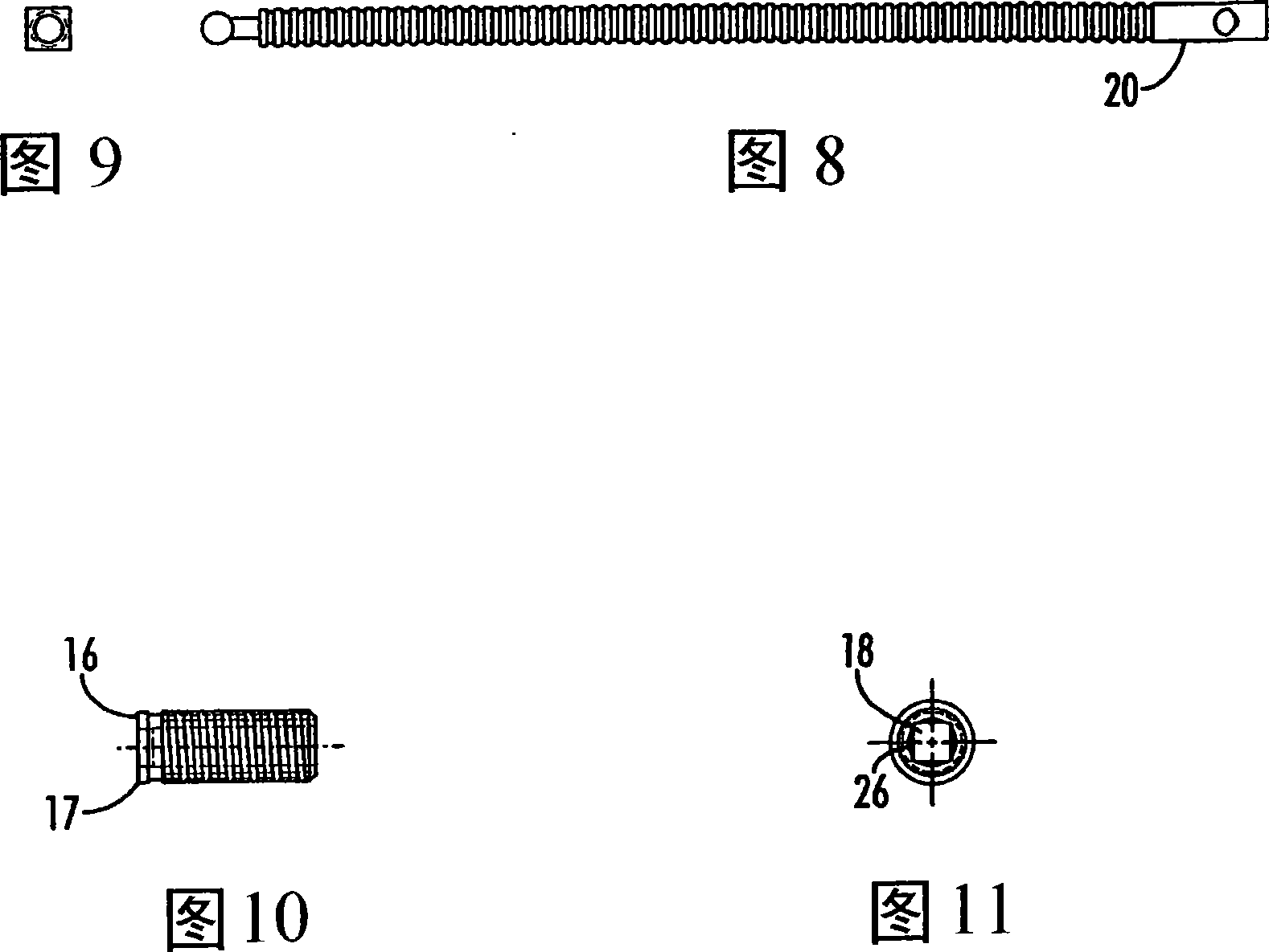
[0020] [20] Figures 1-32 illustrate the quick positioning C-clamp 10 of the present invention. Opening and closing of the quick-positioning C-clamp 10 is a sliding and final screw movement, rather than the basic all-screw method taught by the prior art. The quick positioning "C-shape" clamp 10 is a time saving and labor saving tool. It takes about 1 to 2 minutes to open a traditional 6" "C-shaped" clamp. It takes approximately 2 seconds to open and close the quick position "C-shape" clamp 10 . The arrangement of the present invention also offers advantages over earlier attempts at prior art approaches to C-clamps.
[0021] [21] As shown in Figure 1, the U-shaped or "C-shaped" clamp frame shown as the body 12 is made of cast steel to hold the applied handle 21 through the screw 20 (also called the rod 20) The pressure applied to the support pad 13. The sliding action consists of a square bar lock assembly unit 14 comprising a screw 20 threaded through an internal thread 26 ...
PUM
Abstract
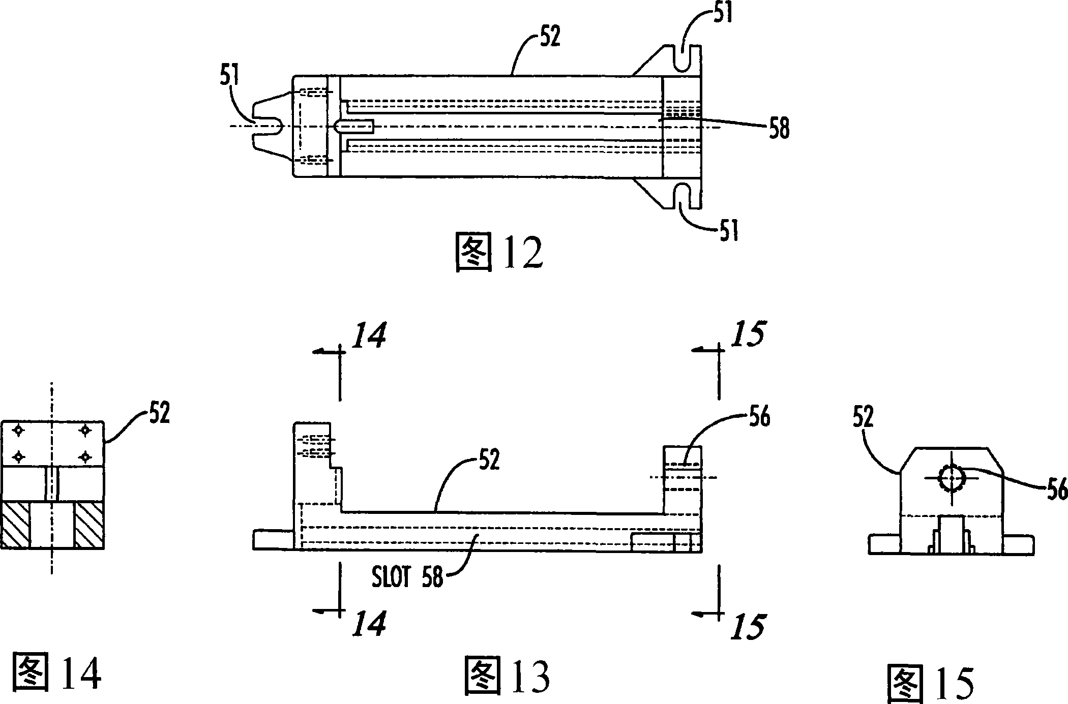
A tension rod positioning apparatus and method including a shaped threaded rod (20) inserted into a shaped threaded hole (22, 56) on an engagement collar (16). When the shaped rod (20) and shaped hole (22, 56) are aligned, the rod (20) may be freely positioned within the collar (16). When the shaped rod (20) is inserted into the collar (16) and turned, the rod (20) engages and turns the engagement collar (16). The engagement collar (16) includes an external thread (29) sized to fit an internal thread (23) on a clamp base (52). The rod (20) may be inserted and then turned to both engage the engagement collar (16) and increase the clamping pressure. The shaped rod (20) may be turned in the opposite direction to loosen the clamping pressure and disengage the engagement collar (16). Once the rod (20) and collar (16) have been disengaged by aligning the shaped rod (20) and shaped hole (22, 56), the rod (20) may be freely moved within the engagement collar (16) to reposition the clamp (10) for the next operation.
Description
technical field [0001] [1] The present invention relates generally to clamping systems, and more particularly, this invention relates to C-clamps and vises, and provides improved quick clamping methods and apparatus for use with these devices. Background technique [0002] [2] Several US patents describe clamping systems. These patents include: U.S. Patent No. 298,704 issued to Norris et al. on May 13, 1884, U.S. Patent No. 823,748 issued to Walden on June 19, 1906, and U.S. Patent No. 823,748 issued to McLean on July 3, 1906 825,151, U.S. Patent No. 947,619 issued to Orr on January 25, 1910, U.S. Patent No. 1,140,646 issued to Abernathy on May 25, 1915, and U.S. Patent No. 2,430,458 issued to Farrell on November 11, 1947 No., US Patent No. 3,357,698 issued to Flynn on December 12, 1967, US Patent No. 3,492,886 issued to Naureckas on February 3, 1970, US Patent No. 4,083,624 issued to Timmer on April 11, 1978, U.S. Patent No. 4,262,892 issued to Wu on April 21, 1981; U.S. ...
Claims
Application Information
Patent Timeline
Application Date:The date an application was filed.
Publication Date:The date a patent or application was officially published.
First Publication Date:The earliest publication date of a patent with the same application number.
Issue Date:Publication date of the patent grant document.
PCT Entry Date:The Entry date of PCT National Phase.
Estimated Expiry Date:The statutory expiry date of a patent right according to the Patent Law, and it is the longest term of protection that the patent right can achieve without the termination of the patent right due to other reasons(Term extension factor has been taken into account ).
Invalid Date:Actual expiry date is based on effective date or publication date of legal transaction data of invalid patent.

