Parallel triaxial main axle journal structure

A spindle head and parallel technology, which is applied in the direction of large fixed members, metal processing machinery parts, metal processing equipment, etc., can solve the problems of high manufacturing cost, huge structure, difficult installation, etc.

Inactive Publication Date: 2007-06-27
TSINGHUA UNIV
View PDF0 Cites 14 Cited by
  • Summary
  • Abstract
  • Description
  • Claims
  • Application Information

AI Technical Summary

Problems solved by technology

These spindle heads often have complex transmission systems, large structures, large moving ma...

Method used


Image

  • Parallel triaxial main axle journal structure

Examples


Embodiment Construction

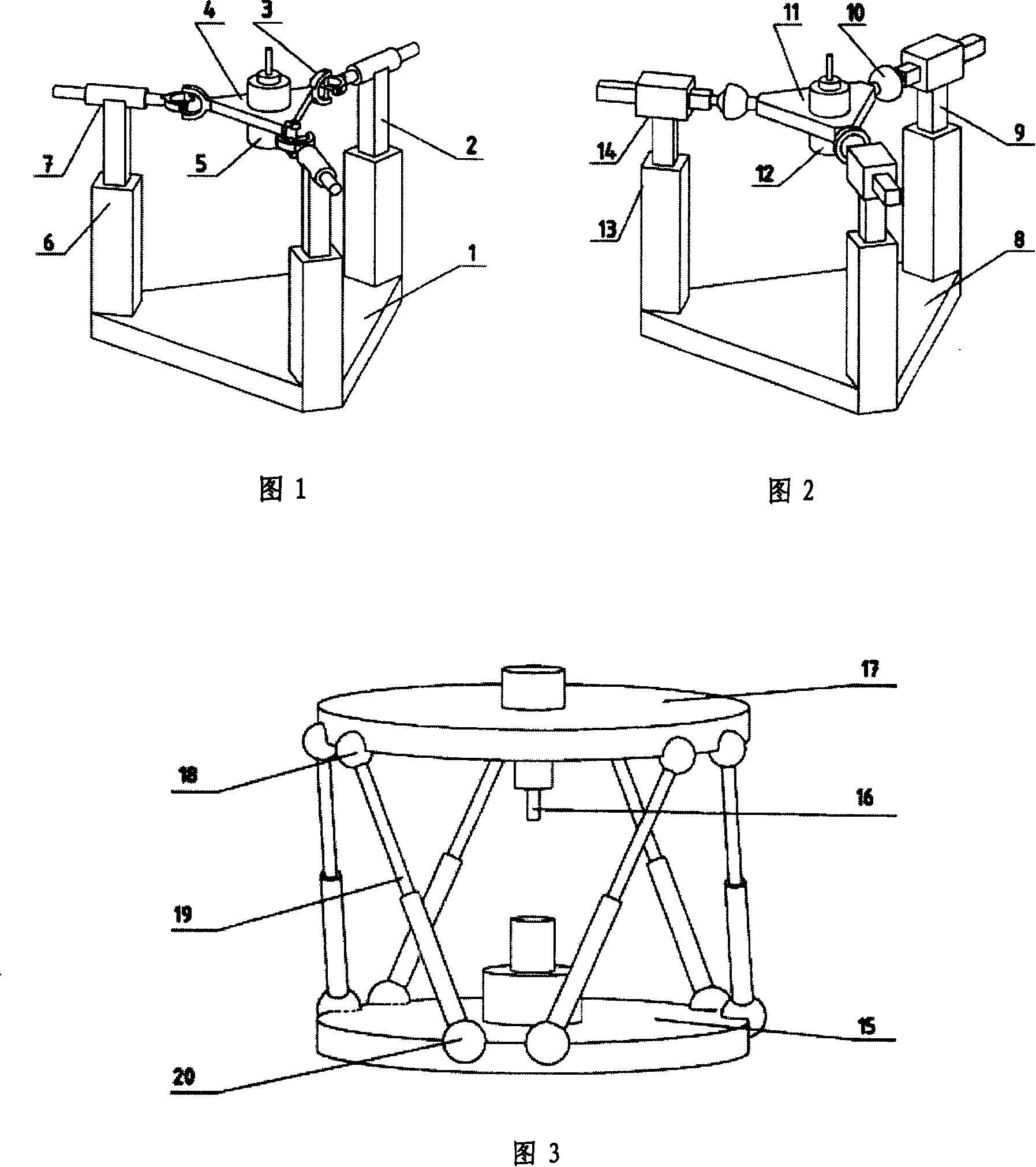
[0013] The parallel three-axis spindle head structure of the present invention is described in detail in conjunction with the accompanying drawings and embodiments as follows: The first embodiment of the parallel three-axis spindle head structure of the present invention is shown in Figure 1. The structure includes: a main shaft, a moving platform, a fixed Platform, and three identical branches connecting the moving platform and the fixed platform, the main shaft is fixed on the moving platform; wherein, the shapes of the moving platform and the fixed platform are equilateral triangles; each branch contains an input rod 2 , a moving pair 6, a cylindrical pair 7 and a universal hinge 3, so the mechanism can be referred to as 3-PCU mechanism. The connection relationship is: the moving platform 4, the three vertices of the moving platform are respectively connected with the three vertices of the fixed platform 1 through three identical branches. One end of the branch connected to...


PUM


Abstract

The present invention is parallel triaxial spindle head structure and belongs to the field of machine building technology. The parallel triaxial spindle head structure includes one spindle, one movable platform, one fixed platform, and three identical branches to connect the movable platform and the fixed platform, with the spindle being fixed onto the movable platform. Each of the three branches includes one input rod member, one multivariant hinge connected to the movable platform, and two kinematic pairs, including one driving one connected between the input rod member and the fixed platform and one driven one connected between the input rod member and the multivariant hinge. The present invention may operate alone or through coordination with other device, and has high rigidity, low moving mass, high dynamic performance, simple structure, low cost and other advantages.

Description

technical field [0001] The invention belongs to the field of mechanical manufacturing, and relates to a parallel three-axis spindle head structure capable of working independently and cooperating with other devices for compound processing. Background technique [0002] At present, a large number of multifunctional milling machines are equipped with a two-axis spindle head that can realize continuous rotation. These spindle heads mostly adopt a tandem structure with double swing angles or fork heads. For example, patent ZL03278067.2 describes an A / C Shaft spindle head and a kind of fork head spindle head proposed by the patent US 3483796. These spindle heads often have complex transmission systems, large structures, large moving masses, and are difficult to install, resulting in high manufacturing costs and high maintenance costs. [0003] In the past ten years, a new concept machine tool - parallel machine tool has appeared in the world. At the Chicago International Manufa...

Claims


Application Information

Patent Timeline
IPC IPC(8): B23Q1/48
Inventor 刘辛军汪劲松吴超王立平李铁民
Owner TSINGHUA UNIV
Why Eureka
Try Eureka