Super thin fan

An ultra-thin, fan-based technology, applied to parts of pumping devices for elastic fluids, non-variable pumps, pump devices, etc., can solve problems such as restrictions and reduction in axial thickness, and achieve simplification of assembly and reduction Axial thickness, combined with simple and reliable results

Inactive Publication Date: 2007-06-27
SUNONWEALTH ELECTRIC MACHINE IND
View PDF1 Cites 8 Cited by
  • Summary
  • Abstract
  • Description
  • Claims
  • Application Information

AI Technical Summary

Problems solved by technology

[0003] Generally speaking, the above-mentioned conventional small fans have the following disadvantages: the rotor shell and fan blades of the fan wheel are usually made by injection molding. In order to ensure the yield of injection molding and adapt to the injection molding machine, the size of the rotor shell occupies a certain volume, it is difficult to further reduce the axial thickness
As a result, the total axial thickness of the rotor part of the conventional small fan is usually greater than 5mm, which will relatively limit the feasibility of further development towards lighter, thinner and shorter

Method used


Image

  • Super thin fan
  • Super thin fan
  • Super thin fan

Examples


Embodiment Construction

[0019] In order to make the purpose, technical features and advantages of the present invention more obvious and understandable, the preferred embodiments of the present invention are specifically cited below, and detailed descriptions are as follows in conjunction with the accompanying drawings:

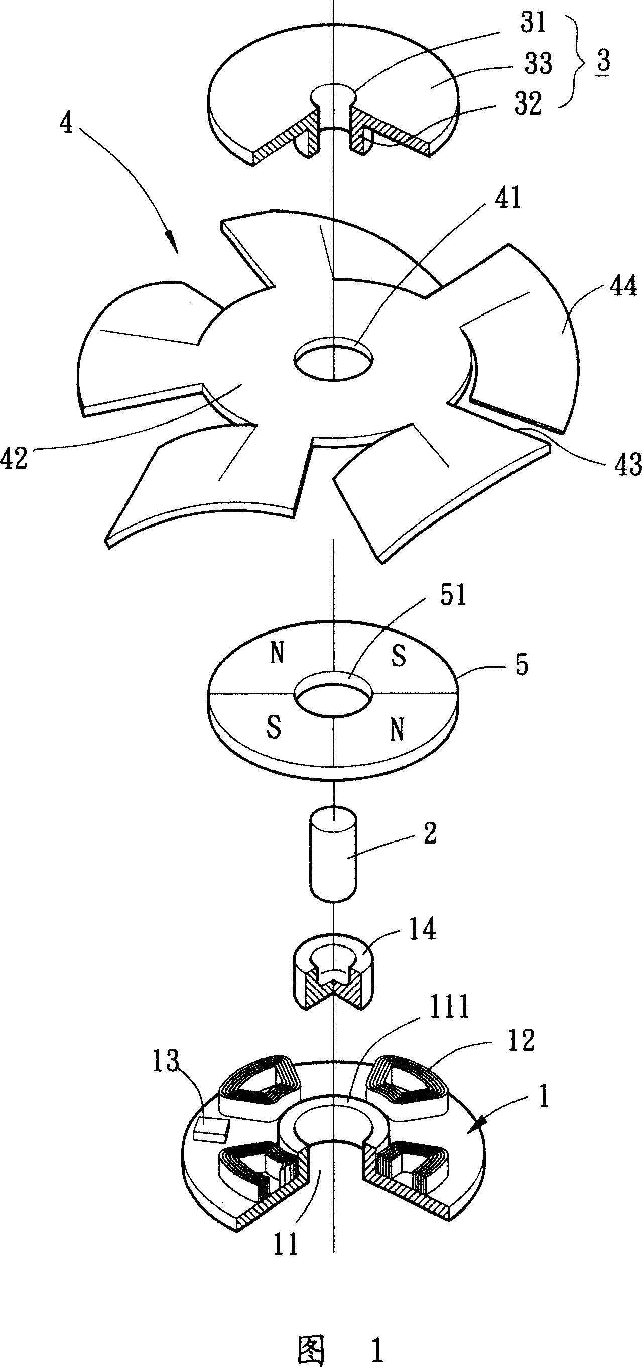
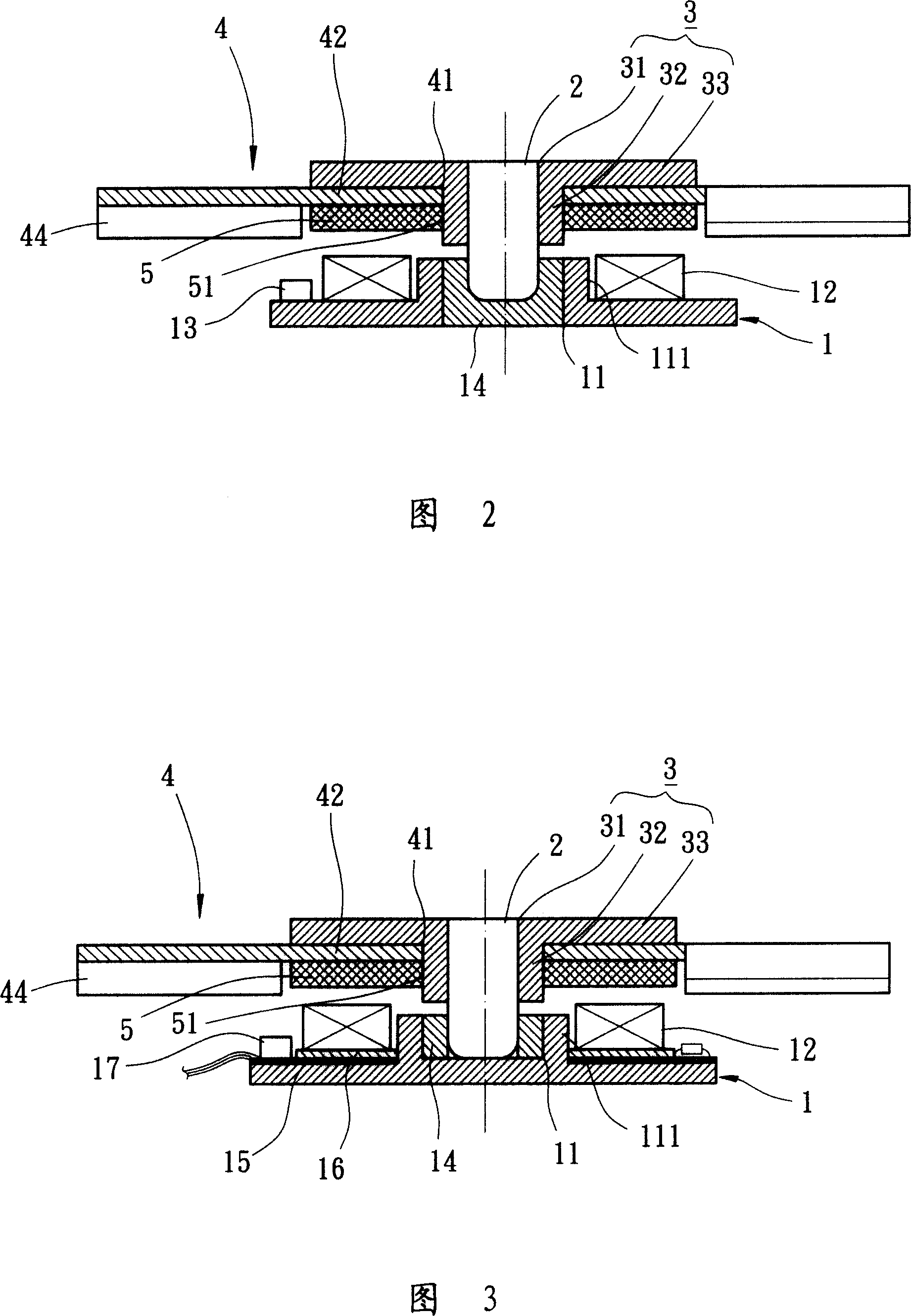
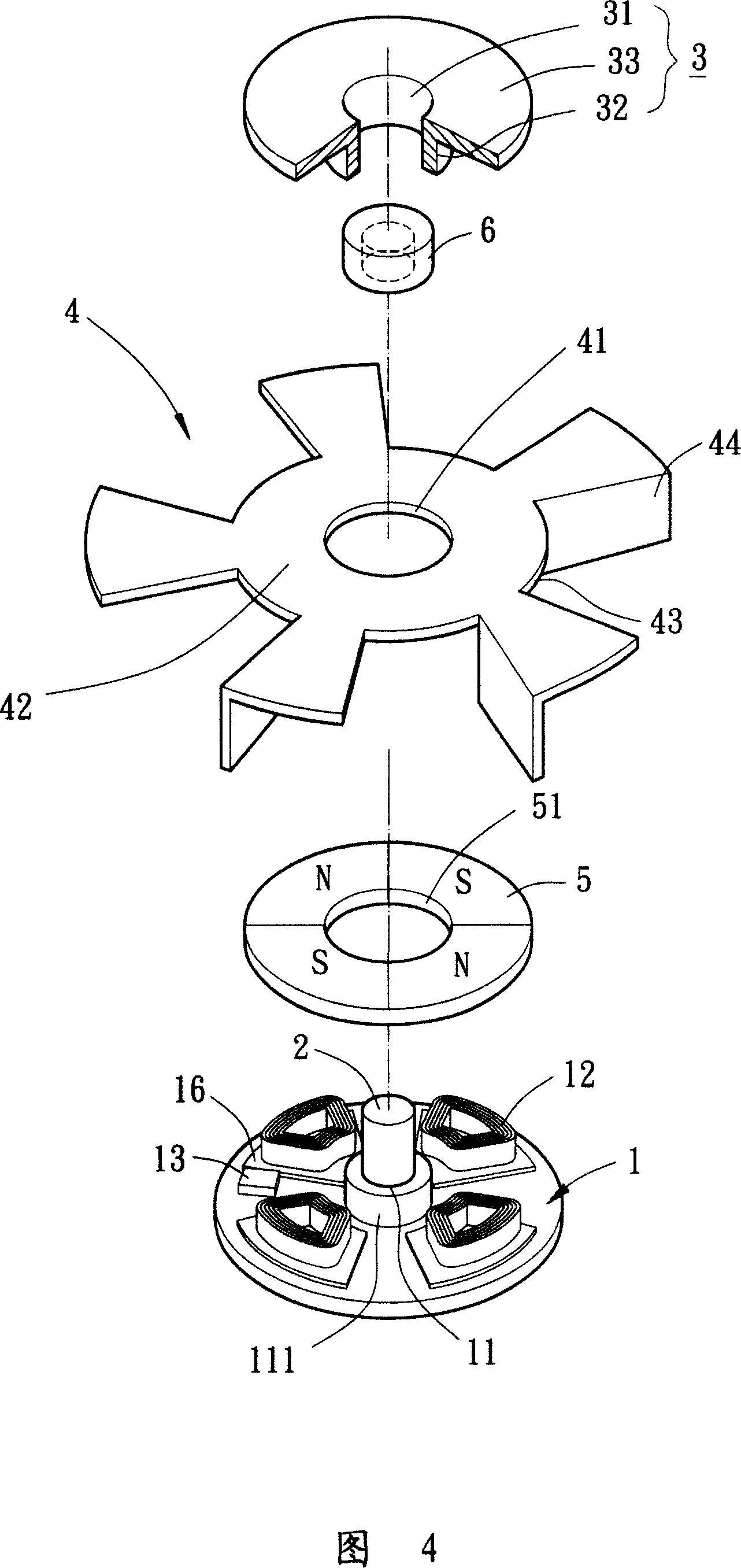
[0020] Referring to FIGS. 1 and 2 , in the first embodiment of the present invention, an ultra-thin fan mainly includes: a base 1 , a shaft 2 , an assembly component 3 , a fan wheel 4 and a sheet magnet 5 . The base 1 can be regarded as a stator component, the shaft 2, assembly element 3, fan wheel 4 and sheet magnet 5 can be regarded as a rotor component, and according to product requirements, the total axial thickness of the rotor component can even be reduced to Below 3mm.

[0021] Please refer to FIGS. 1 and 2 , the base 1 is preferably made of magnetically permeable material, such as iron or iron alloy. The base 1 is provided with a shaft hole 11 , at least one coil 12 , a dri...


PUM


Abstract

An ultra-thin fan is composed of a base with an axle hole and at least one coil, a blade wheel consisting of an annular plate and multiple curved blades, an assembly elements with an assembling hole and a radial flange, a magnet sheet with at least one pair of N and S poles on its surface, and an axle.

Description

technical field [0001] The invention relates to a fan, in particular to an ultra-thin fan that directly forms a fan wheel by a ring plate and a plurality of bent fan blades, can reduce the overall axial thickness of the fan, is simple and reliable to assemble, and increases the starting balance and rotation stability of the fan wheel. Background technique [0002] Conventional fans, such as the invention patent of US Patent No. 5,217,351 "Small Fan (Small Fan)", include a housing and a fan wheel. There is a base inside the casing, and a shaft tube and two coils are arranged on the base, a bearing is arranged inside the shaft tube, and the two coils are flat. The fan wheel has a rotor shell, a plurality of fan blades, a shaft and a ring magnet. The rotor shell is in the shape of an inverted bowl, and a plurality of fan blades are arranged radially at equal distances on its outer peripheral surface. One end of the shaft rod is fixed in the center of the rotor shell, and the ...

Claims


Application Information

Patent Timeline
Patent Type & Authority Applications(China)
IPC IPC(8): F04D25/08F04D29/30F04D29/62F04D29/00F04D29/66F04D29/054F04D29/056
Inventor 洪银树尹佐国
Owner SUNONWEALTH ELECTRIC MACHINE IND
Why Eureka
Try Eureka