Method for controlling light charge quantity of light sensing LED and its image sensor

A photodiode and image sensing technology, applied in lighting devices, electroluminescent light sources, light sources, etc., can solve the problems of difficult control process, halo phenomenon, image retention, etc., to avoid image retention and halo phenomenon, Low cost and accurate charge size

Inactive Publication Date: 2007-06-27
PIXART IMAGING INC
View PDF0 Cites 4 Cited by
  • Summary
  • Abstract
  • Description
  • Claims
  • Application Information

AI Technical Summary

Problems solved by technology

[0005] The prior art Active Pixel 8 has two disadvantages: one is the halo phenomenon; the other is the problem of image retention, which will be explained separately below
However, the control process is not easy and the cost is too high, so a simpler control method is needed to solve the problem of image retention

Method used


Image

  • Method for controlling light charge quantity of light sensing LED and its image sensor
  • Method for controlling light charge quantity of light sensing LED and its image sensor
  • Method for controlling light charge quantity of light sensing LED and its image sensor

Examples


Embodiment Construction

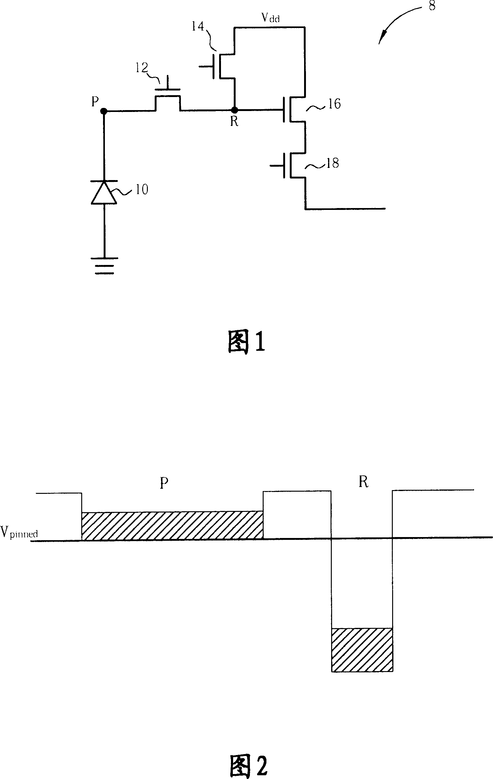
[0047] The present invention provides a method for controlling the amount of charge that can be stored in the clamped photodiode 10 to solve the problems of image retention and halo phenomenon in the prior art.

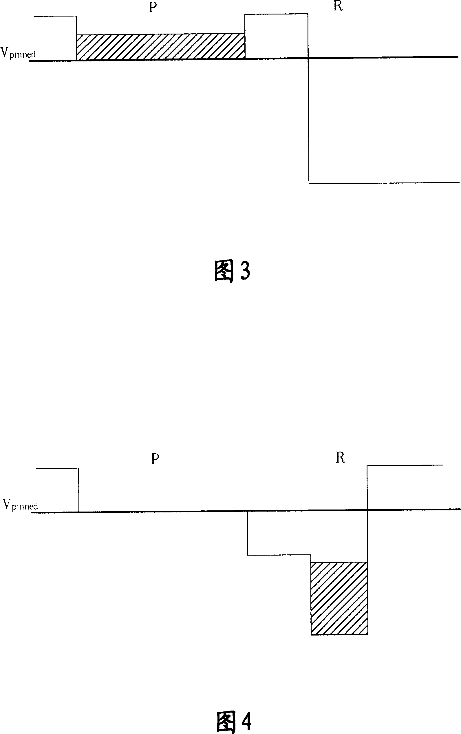
[0048] First, the concept of the present invention will be explained. Image retention occurs because the charge in the clamped photodiode 10 cannot be completely transferred. Therefore, if the charge capacity that can be stored in the clamped photodiode 10 is reduced, the image retention phenomenon can be avoided. In addition, the halo phenomenon is caused by receiving too much light charge, causing the light charge to overflow to surrounding pixels. Therefore, the generation of the halo phenomenon can also be reduced by controlling the charge capacity that can be stored in the pinched photodiode 10 .

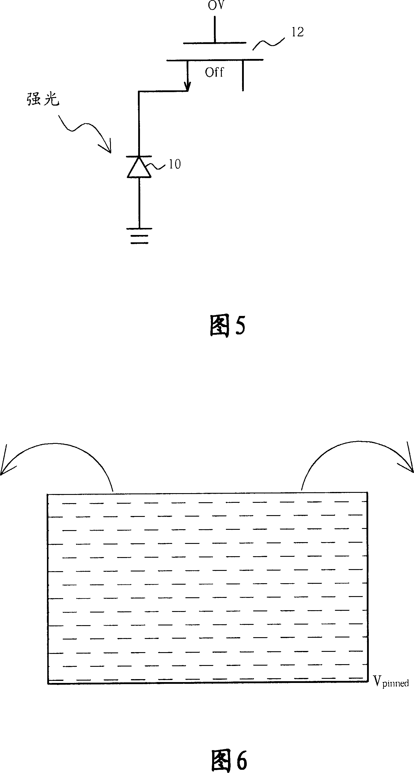
[0049] Please refer to FIG. 8 . FIG. 8 is a schematic diagram of the switching transistor 12 and the clamping photodiode 10 . When supplied with a voltage V g When...


PUM


Abstract

This invention relates to a method for measuring photoelectric charges of a light sensing diode in controllable active pixels and a sensing device, in which, the method includes: providing a reference voltage greater than the earth potential to the grid of a converted transistor when a light sensing diode is exposed and one end of which contacts to the earth to control the photoelectric charges stored by light sensing diode, which advoides image resort and halation.

Description

technical field [0001] The invention provides a method for controlling active pixels, especially a method for controlling the amount of photoelectric charges that can be stored in a photodiode and an image sensing device thereof. Background technique [0002] Please refer to FIG. 1 , which is a circuit diagram of the previous active pixel 8 . The active pixel 8 includes a pinned photodiode 10, a transfer transistor 12, a reset transistor 14, a source follower 16 and a row selector. ) transistor 18. The clamping photodiode 10 is used to receive light; the switching transistor 12 is used to control the charge transfer stored in the clamping photodiode 10; the reset transistor 14 is used to reset the clamping photodiode 10; the source of the source follower 16 The potential of the electrode will change with the charge received by the gate of the source follower 16; the column selection switch transistor 18 is used to control the storage of the optical signal or the reset sign...

Claims


Application Information

Patent Timeline
Patent Type & Authority Applications(China)
IPC IPC(8): G09G3/32G09G3/30G09G3/20H05B33/08H05B33/14H05B44/00
Inventor 苏明俊黄建章谢志成
Owner PIXART IMAGING INC
Why Eureka
Try Eureka