Direct-type fuel cell and direct-type fuel cell system

一种燃料电池、直接的技术,应用在燃料电池、燃料电池助剂、燃料电池的零部件等方向,能够解决没有提出阴极、燃料量不足、放电性能减弱等问题,达到抑制燃料使用率的下降、抑制燃料使用率的降低、减少穿越现象的效果

Inactive Publication Date: 2010-09-22
PANASONIC CORP
View PDF5 Cites 0 Cited by
  • Summary
  • Abstract
  • Description
  • Claims
  • Application Information

AI Technical Summary

Problems solved by technology

[0013] The second problem is to prevent the cathode from being clogged with water (flooding) and drying of the MEA
Also, if a small amount of high-concentration methanol solution that is very close to the consumption required for power generation is supplied, the amount of fuel downstream of the fuel passage becomes insufficient, thus causing a significant reduction in discharge performance
[0018] In addition, in the fuel cells of Japanese Patent Application No. 2002-110191 and No. 2002-247091, since the mixed layer and lining layer are present on the anode side, the emission rate of carbon dioxide as a reaction product decreases
Therefore, the discharge performance at high current densities may be degraded
[0019] In addition, Japanese Patent Application No. 2002-247091 does not propose a special method to solve the problem of cathode clogging by water that occurs when the air flow rate is low

Method used


Image

  • Direct-type fuel cell and direct-type fuel cell system
  • Direct-type fuel cell and direct-type fuel cell system
  • Direct-type fuel cell and direct-type fuel cell system

Examples


Embodiment 1

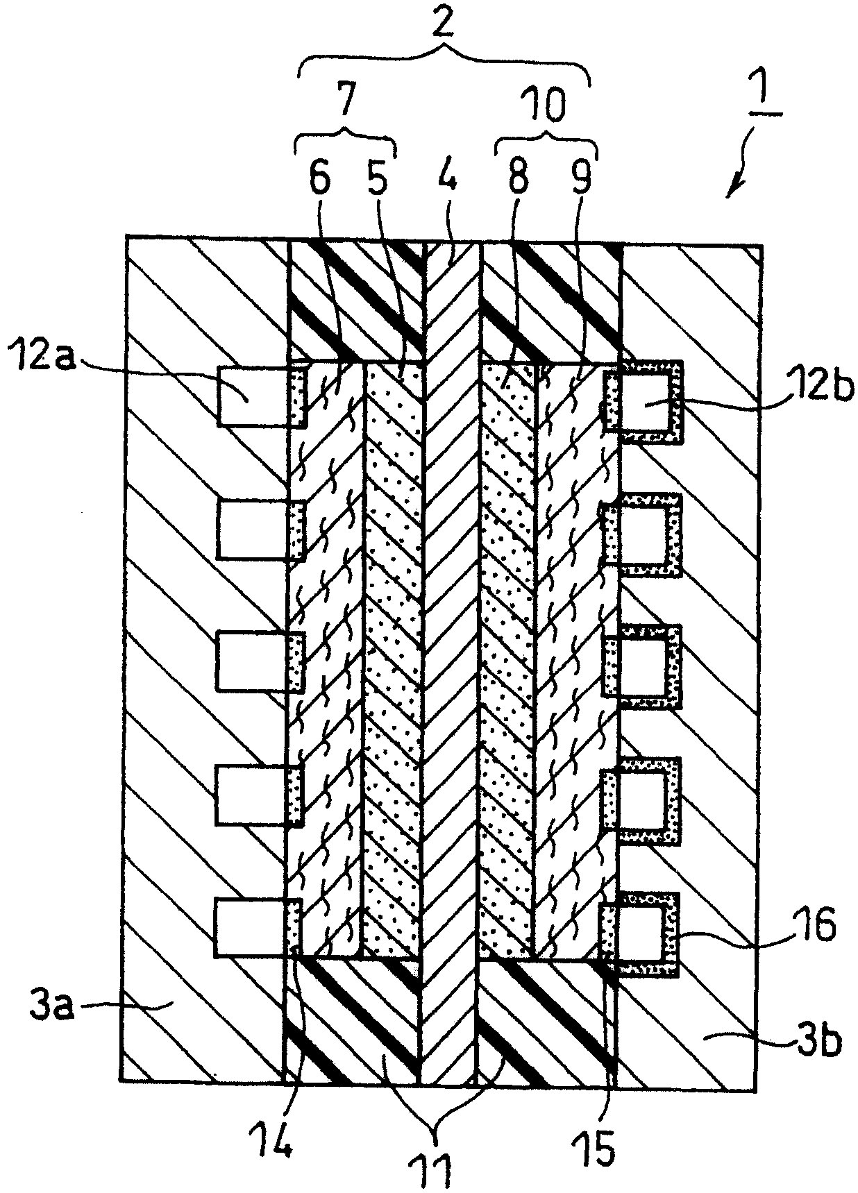
[0095] Prepare a figure 1 The fuel cell shown.

[0096] (i) Anode side catalyst layer

[0097] The anode-supported catalyst particles are prepared by loading 30 wt% of platinum particles and 30 wt% of ruthenium particles on conductive carbon black particles. The average particle size of platinum particles and ruthenium particles are both 3nm, while the average primary particle size of carbon black particles is 30nm (ketjen black EC, purchased from Mitsubishi Chemical Company).

[0098] The isopropanol aqueous solution in which anode-supported catalyst particles are dispersed and the polymer electrolyte in ethanol are mixed. The mixed solution was stirred in a ball mill to prepare an anode catalyst paste. The weight percentage of conductive carbon black particles and polymer electrolyte in the anode catalyst paste is 2:1. The electrolyte used was perfluorocarbon sulfonic acid ionomer (Flemion, purchased from Asahi Glass Co., Ltd.).

[0099] Use a medical scraper to apply the anode c...

Embodiment 2

[0111] When the diffusion surface layer 14 (PTFE / silicone resin layer) is formed on the anode side diffusion layer 6 substrate, the number of repetitions of spraying and air drying is changed, and the high temperature drying temperature is changed to 80°C for 60 minutes to make the diffusion surface The thickness of the layer 14 becomes about 100 μm. Except for these modifications, a fuel cell (cell B) was prepared in the same method as in Example 1.

Embodiment 3

[0113] Carbon paper (TGP-060, available from Toray Industries) with a thickness of 180 μm was used instead of TGP-H120 as the substrate of the anode-side diffusion layer 6. At the same time, when the diffusion surface layer 14 (PTFE / silicone resin layer) is formed on the substrate of the diffusion layer 6 on the anode side, the number of repetitions of spraying and air drying is changed, and the high-temperature drying temperature is changed to 70°C for 20 minutes, thereby The thickness of the diffusion surface layer 14 is changed to about 5 μm. Except for these modifications, a fuel cell (cell C) was prepared in the same manner as in Example 1.


PUM

PropertyMeasurementUnit
surface tensionaaaaaaaaaa
viewing angleaaaaaaaaaa

Abstract

A direct-type fuel cell having excellent power generating characteristics even under operating conditions utilizing a high concentration fuel at low air flow rates. The anode includes an anode-side diffusion layer that faces the fuel flow channel and an anode-side catalyst layer in contact with the electrolyte membrane. The cathode includes a cathode-side diffusion layer that faces the air flow channel and a cathode-side catalyst layer in contact with the electrolyte membrane. A surface area of the anode-side diffusion layer facing the fuel flow channel or both a surface area of the anode-side diffusion layer facing the fuel flow channel and a surface area of the cathode-side diffusion layer facing the air flow channel have a critical surface tension of penetrating wettability of 22 to 40mN / m.

Description

Technical field [0001] The present invention relates to a direct fuel cell that directly uses fuel without converting it into hydrogen, and a system including the fuel cell. Background technique [0002] Recently, portable small electronic products such as mobile phones, personal digital assistants (PDAs), notebook computers, and cameras have become more and more complex, and at the same time, the power consumption and power maintenance time requirements of these electronic products have been increasing. In order to solve these problems, the power supply of these electronic products needs to have a higher energy density. Recently, the power supply of these electronic products mainly uses lithium-ion batteries, but it is expected that by 2006, lithium batteries will reach their energy density limit, which is about 600Wh / L. As an energy source that can replace lithium-ion batteries, people hope that fuel cells using polymer electrolyte membranes can enter the practical field as so...

Claims


Application Information

Patent Timeline
Patent Type & Authority Patents(China)
IPC IPC(8): H01M8/10H01M8/02H01M4/86H01M8/04
CPCH01M2008/1095H01M8/0239H01M8/04194Y02E60/523H01M8/1009Y02E60/50H01M8/02H01M4/86
Inventor 植田英之福田真介秋山崇
Owner PANASONIC CORP
Why Eureka
Try Eureka