Direct-type fuel cell and direct-type fuel cell system

A fuel cell, direct technology, applied in the direction of fuel cells, fuel cell additives, fuel cell components, etc., can solve the problems of insufficient fuel, no cathode, and weakened discharge performance, etc., to achieve the reduction of fuel usage rate , The effect of suppressing the decline of fuel usage rate and reducing the phenomenon of crossing

Inactive Publication Date: 2007-06-27
PANASONIC CORP
View PDF5 Cites 3 Cited by
  • Summary
  • Abstract
  • Description
  • Claims
  • Application Information

AI Technical Summary

Problems solved by technology

[0013] The second problem is to prevent the cathode from being clogged with water (flooding) and drying of the MEA
Also, if a small amount of high-concentration methanol solution that is very close to the consumption required for power generation is supplied, the amount of fuel downstream of the fuel passage becomes insufficient, thus causing a significant reduction in discharge performance
[0018] In addition, in the fuel cells of Japanese Patent Application No. 2002-110191 and No. 2002-247091, since the mixed layer and lining layer are present on the anode side, the emission rate of carbon dioxide as a reaction product decreases
Therefore, the discharge performance at high current densities may be degraded
[0019] In addition, Japanese Patent Application No. 2002-247091 does not propose a special method to solve the problem of cathode clogging by water that occurs when the air flow rate is low

Method used


Image

  • Direct-type fuel cell and direct-type fuel cell system
  • Direct-type fuel cell and direct-type fuel cell system

Examples


Embodiment 1

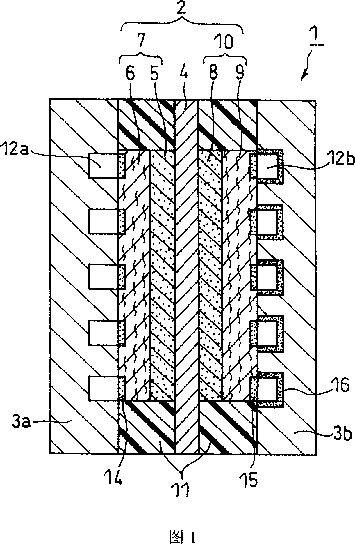
[0095] A fuel cell as shown in Figure 1 was prepared.

[0096] (i) Catalyst layer on the anode side

[0097] Anode-supported catalyst particles were prepared by loading 30 wt% of platinum microparticles and 30 wt% of ruthenium microparticles on conductive carbon black particles. The average particle size of platinum particles and ruthenium particles is 3 nm, and the average primary particle size of carbon black particles is 30 nm (ketjen black EC, purchased from Mitsubishi Chemical Company).

[0098] The isopropanol aqueous solution in which the anode-supported catalyst particles were dispersed was mixed with the ethanol in which the polymer electrolyte was dispersed. The mixed solution was stirred in a ball mill to prepare an anode catalyst paste. The weight percentage of conductive carbon black particles and polymer electrolyte in the anode catalyst paste is 2:1. The electrolyte used was perfluorocarbon sulfonic acid ionomer (Flemion, available from Asahi Glass Co., Ltd.)...

Embodiment 2

[0111] When forming the diffusion surface layer 14 (PTFE / silicone resin layer) on the substrate of the diffusion layer 6 on the anode side, change the number of repetitions of spraying and air drying, and change the high-temperature drying temperature to 80°C for 60 minutes, so that the diffusion surface The thickness of layer 14 becomes about 100 μm. A fuel cell (cell B) was prepared in the same manner as in Example 1 except for these modifications.

Embodiment 3

[0113] Carbon paper (TGP-060, purchased from Toray Industries) with a thickness of 180 μm was used instead of TGP-H120 as the substrate of the diffusion layer 6 on the anode side. Simultaneously, when forming the diffusion surface layer 14 (PTFE / silicone resin layer) on the substrate of the diffusion layer 6 on the anode side, change the number of repetitions of spraying and air drying, and change the high-temperature drying temperature into 70° C. and dry for 20 minutes, thereby The thickness of the diffusion surface layer 14 was made to be about 5 μm. A fuel cell (cell C) was prepared in the same manner as in Example 1 except for these modifications.


PUM

PropertyMeasurementUnit
critical surface tensionaaaaaaaaaa
surface tensionaaaaaaaaaa

Abstract

A direct-type fuel cell having excellent power generating characteristics even under operating conditions utilizing a high concentration fuel at low air flow rates. The anode includes an anode-side diffusion layer that faces the fuel flow channel and an anode-side catalyst layer in contact with the electrolyte membrane. The cathode includes a cathode-side diffusion layer that faces the air flow channel and a cathode-side catalyst layer in contact with the electrolyte membrane. A surface area of the anode-side diffusion layer facing the fuel flow channel or both a surface area of the anode-side diffusion layer facing the fuel flow channel and a surface area of the cathode-side diffusion layer facing the air flow channel have a critical surface tension of penetrating wettability of 22 to 40 mN / m.

Description

technical field [0001] The present invention relates to a direct type fuel cell that directly uses fuel without converting it into hydrogen, and a system including the fuel cell. Background technique [0002] Recently, portable small electronic products such as mobile phones, personal digital assistants (PDAs), notebook computers, and cameras have become more and more complex, and the requirements for power consumption and power maintenance time of these electronic products have been increasing. In order to solve these problems, the power supplies of these electronic products need to have higher energy density. Recently, the power supply of these electronic products mainly uses lithium-ion batteries, but it is expected that by about 2006, lithium batteries will reach their energy density limit, that is, about 600Wh / L. As an energy source that can replace lithium-ion batteries, it is hoped that fuel cells using polymer electrolyte membranes can enter the practical field as s...

Claims


Application Information

Patent Timeline
Patent Type & Authority Applications(China)
IPC IPC(8): H01M8/10H01M8/02H01M4/86H01M8/04
CPCY02E60/50H01M8/0239Y02E60/523H01M2008/1095H01M8/1009H01M8/04194H01M8/02H01M4/86
Inventor 植田英之福田真介秋山崇
Owner PANASONIC CORP
Why Eureka
Try Eureka