
Electrical device, particularly relay socket, with spring clip and method of manufacture

A technology of relay sockets and electrical components, applied in electromagnetic relays, electromagnetic relay details, relays, etc., can solve the problems of complex installation and operation, and achieve the effect of reliable contact

Active Publication Date: 2007-06-27
TYCO ELECTRONICS AUSTRIA
View PDF0 Cites 8 Cited by
  • Summary
  • Abstract
  • Description
  • Claims
  • Application Information

AI Technical Summary

Problems solved by technology

However, installation and operation of multiple screw clamps is complicated, one screw clamp for each terminal

Method used


Image

  • Electrical device, particularly relay socket, with spring clip and method of manufacture
  • Electrical device, particularly relay socket, with spring clip and method of manufacture
  • Electrical device, particularly relay socket, with spring clip and method of manufacture

Examples


Embodiment Construction

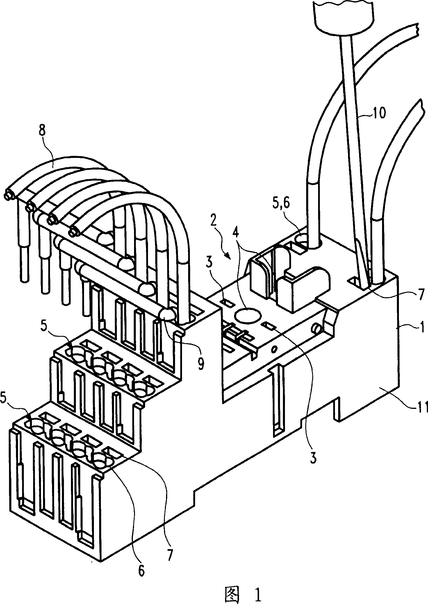
[0035] FIG. 1 shows a relay socket 1 as an electrical component to which the present invention is applied. The relay socket 1 receives a relay (not shown) in a receiving area 2 provided with plug contacts 3 for a relay plug (not shown) and for precise positioning of the relay (not shown) in the receiving area 2 The positioning device 4.

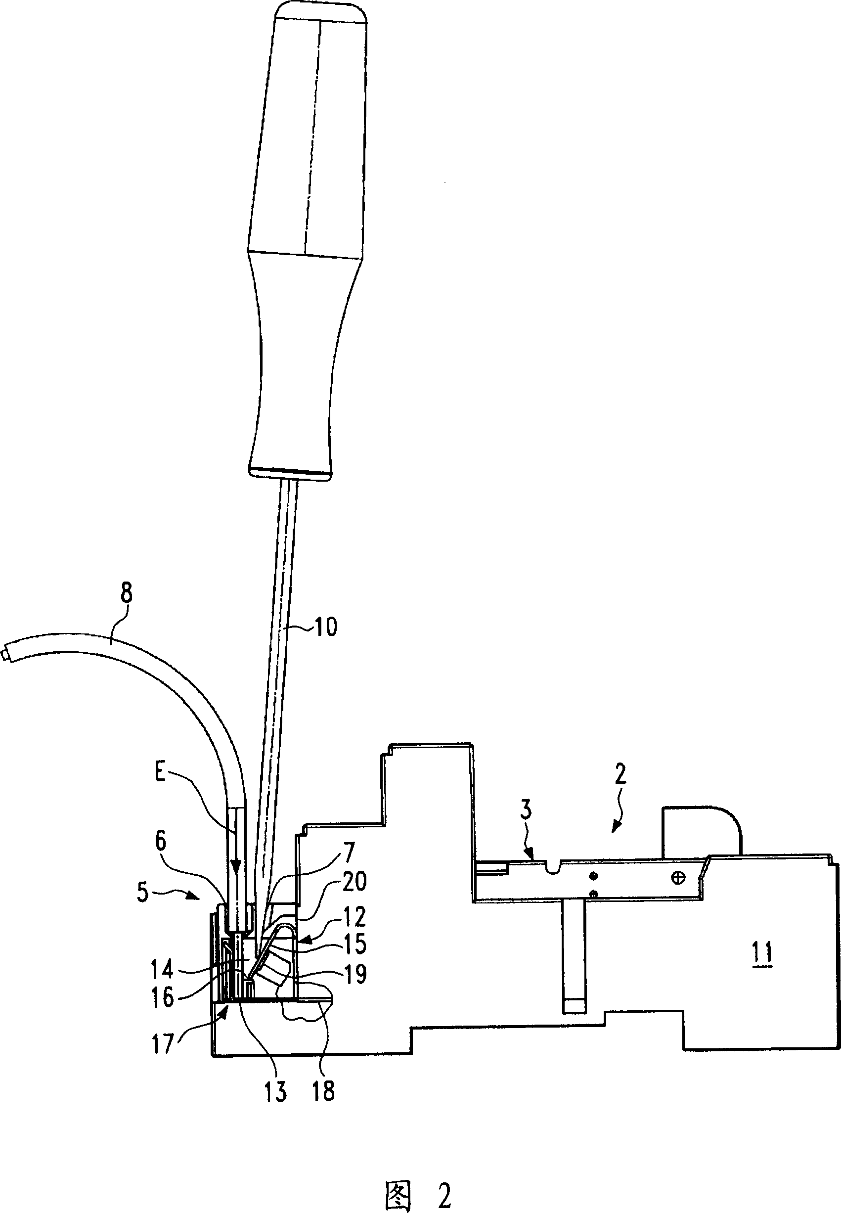
[0036] The relay socket 1 is provided with a plurality of terminals 5 connected to plug contacts 3 for relays (not shown) through conductor elements (not shown in FIG. 1 ). The terminals 5 are each provided with at least one insertion opening 6 and at least one actuation opening 7 .

[0037] At least one conductor 8 and / or at least one connection part 9 can be pushed into the insertion opening 6 . The inner contour of the insertion opening 6 corresponds to the outer contour of the connecting parts 9 or conductors 8 arranged adjacent to each other, with the result that these elements are individually supported and positioned by the walls of ...


PUM


Abstract

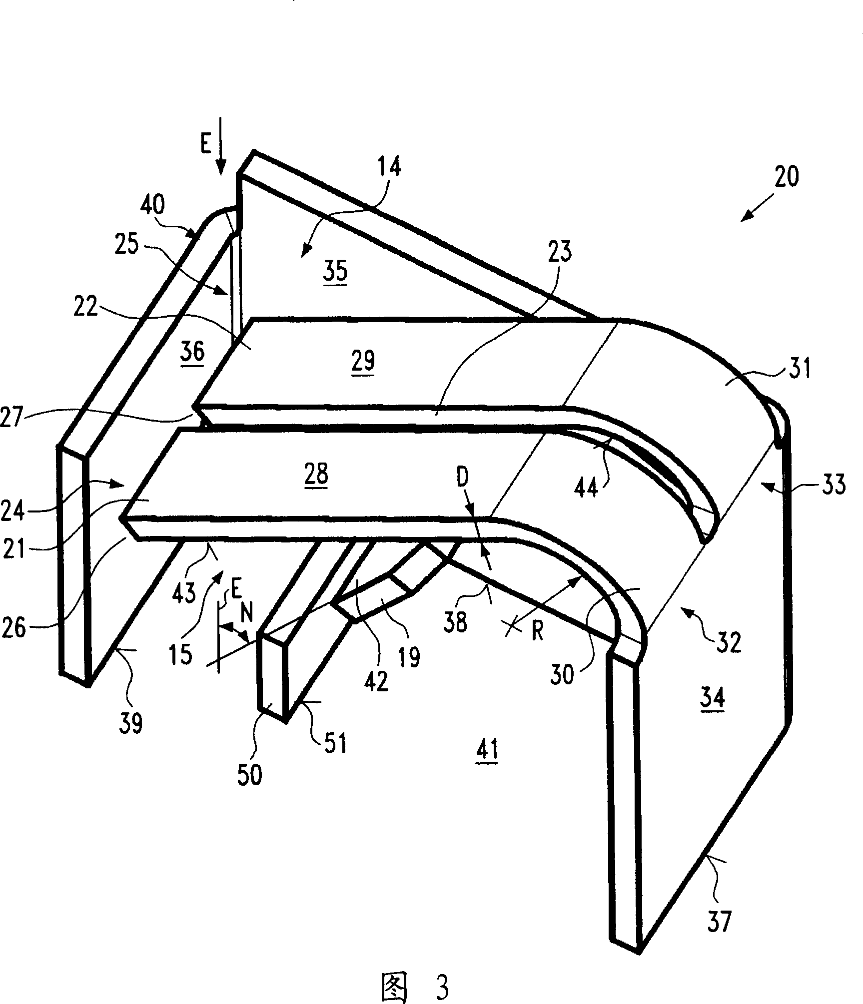
Electrical device has a housing having a terminal provided with an insertion opening configured for receiving a conductor end. The insertion opening communicates with an assembly chamber formed in the terminal. A clamp is arranged in the assembly chamber. The clamp has a leaf spring (15) divided into two parallel spring contacts (21, 22) by a parting slot. Each spring contacts is deflectable in a direction of insertion of the conductor end and having a free end (24, 25) positioned adjacent to a contact pressure plate so that a clamping slot is formed there between that force-fittingly receives the conductor end. The electrical device is a relay socket. An independent claim is included for a method of manufacture.

Description

technical field [0001] The invention relates to an electrical component, in particular a relay socket, having a housing and at least one terminal for connecting at least one conductor end. The terminal is provided with at least one insertion opening extending in a direction in which the conductor end is inserted into a conductor receiving cavity provided inside the housing, and has a clamping device allowing the conductor end to be press-fittedly fixed in the conductor receiving cavity. Background technique [0002] Electrical components of this type are already known in the prior art. For example, screw clamps or cable clamps are used to connect conductor ends, wherein the conductor ends are introduced into clamping grooves defined by conductive contact pressure plates, and the contact pressure plates are then pressed against the conductor ends by screws to secure the clamps. The tight groove narrows. This creates a force-fit connection between the conductor end and the e...

Claims


Application Information

Patent Timeline
Patent Type & Authority Applications(China)
IPC IPC(8): H01R4/48H01R43/16H01H45/14
CPCH01R4/4827H01H50/14H01R9/26H01R43/20H01R4/48275
Inventor 约翰尼斯·赫尔姆赖克
Owner TYCO ELECTRONICS AUSTRIA
Learn More