Duty-cycle correction circuit and method for differential clocking

A differential correction, differential clock technology, applied in electrical components, converting continuous pulse trains into pulse train devices with required patterns, pulse technology, etc., can solve large-area, single-ended feedback circuits that are prone to noise, high power And other issues

Inactive Publication Date: 2007-06-27
INT BUSINESS MASCH CORP
View PDF2 Cites 22 Cited by
  • Summary
  • Abstract
  • Description
  • Claims
  • Application Information

AI Technical Summary

Problems solved by technology

However, these single-ended feedback circuits are prone to noise and require additional circuitry to convert between differential and single-ended signaling
In addition, the design requires a large area due to the use of replicators and other feedback conversion devices
In summary, these circuits have inherent problems of poor noise rejection, duty cycle distortion, higher power and larger area

Method used


Image

  • Duty-cycle correction circuit and method for differential clocking
  • Duty-cycle correction circuit and method for differential clocking
  • Duty-cycle correction circuit and method for differential clocking

Examples


Embodiment Construction

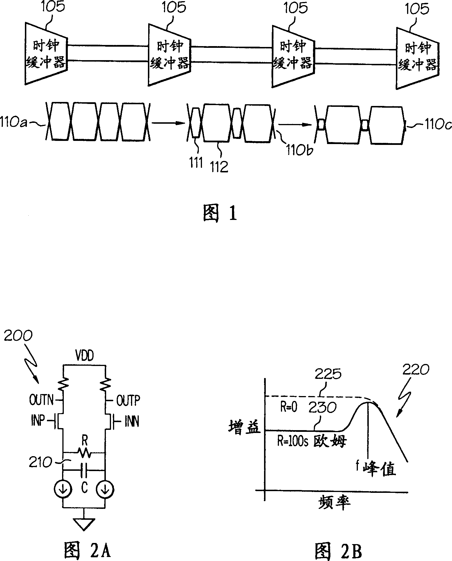
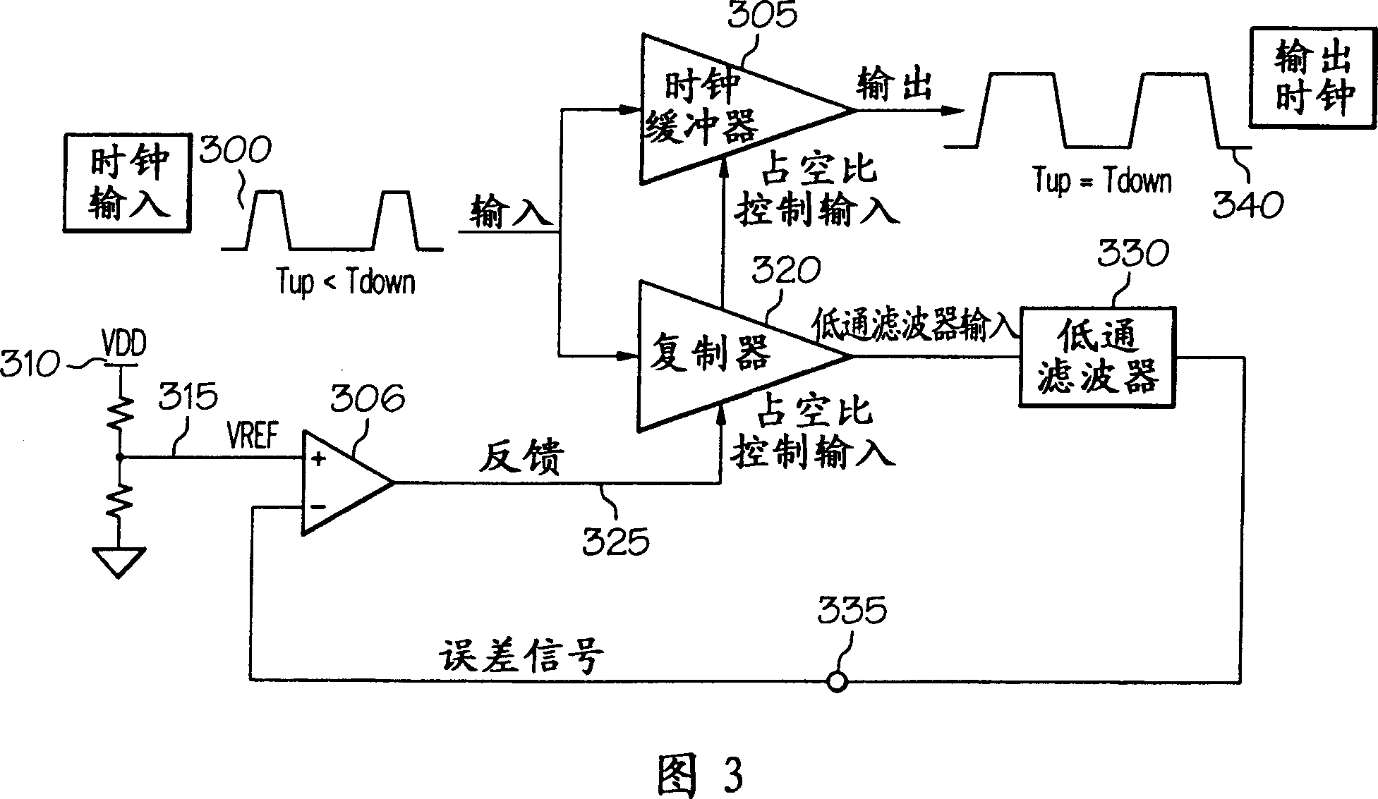
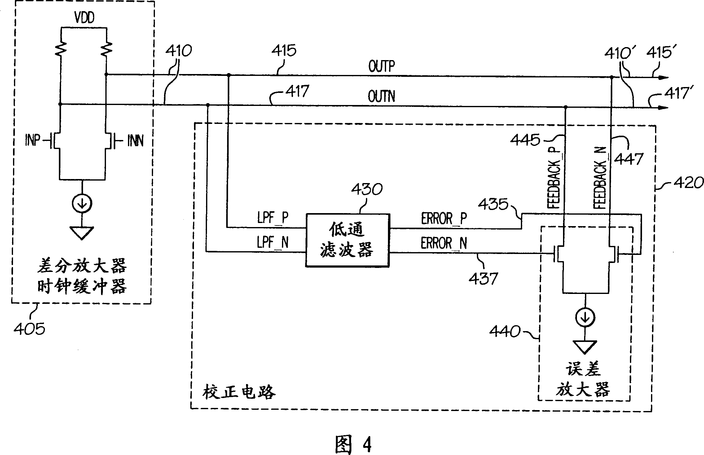
[0019] The present invention provides a circuit design and method for correcting duty cycle distortion of a differential clock signal propagating through a differential amplifier (or clock buffer). The circuit components employed include a differential amplifier, a low pass filter, and a correction current source combined into a simple two-stage amplifier circuit with a correction output dotted to the differential output of the differential buffer.

[0020] The correction circuit is connected to both the (differential) output pulses / signals from the differential amplifier. The correction circuit includes: a differential low pass filter which filters out the DC (direct current) component of each output pulse / signal of the differential output; and a differential error amplifier which compares the DC outputs from the low pass filter and generates a pair of The differential error adjusts the DC current. The differential error adjusting DC current is then fed back to each pulse of...


PUM


Abstract

A completely differential approach to correcting duty-cycle distortions of a differential clock signal propagating through a differential amplifier. A duty-cycle distortion correction (DCDC) differential amplifier circuit / device is provided with a differential amplifier whose output wires are coupled to a correction circuit. The correction circuit comprises a differential low pass filter and a differential correction amplifier. The differential correction amplifier's output is dotted back into the output of the amplifier. The differential output of the amplifier is passed through the low pass filter, which provides differential DC output signals that triggers respective correction amplifier transistors to generate an inverted correction current that is added back to respective differential output pulse. The DCDC differential amplifier provides a completely differential approach to correction of duty-cycle distortions within the differential output.

Description

technical field [0001] The present invention relates generally to circuit devices, and more particularly to signal propagation through circuit devices. More specifically, the present invention relates to methods and circuit devices for correcting duty cycle distortion in a signal propagating through a circuit device. Background technique [0002] Duty cycle in a circuit device is a measure of the rise pulse time of a clock signal propagating through the device compared to the cycle time. For many current device implementations, these clock signals are differential clock signals (rather than single-ended clock signals), and their duty cycles tend to exhibit distortion as they propagate through the device. [0003] For example, a conventional circuit device such as an ASIC (Application Specific Integrated Circuit) receives and propagates a differential clock input signal with rising and falling pulses through a differential clock tree consisting of a series of amplifiers (or ...

Claims


Application Information

Patent Timeline
Patent Type & Authority Applications(China)
IPC IPC(8): H03K5/156
CPCH03K5/1565
Inventor A·德瓦卡J·M·史蒂文斯
Owner INT BUSINESS MASCH CORP
Why Eureka
Try Eureka