
Shift control device and shift control method for vehicle

A technology of speed change device and control device, which is applied in the direction of control device, non-electric variable control, speed/acceleration control, etc., to achieve the effect of reducing the impact of speed change

Inactive Publication Date: 2007-06-27
KOMATSU LTD
View PDF2 Cites 19 Cited by
  • Summary
  • Abstract
  • Description
  • Claims
  • Application Information

AI Technical Summary

Problems solved by technology

[0015] The present invention is developed in view of such actual conditions, therefore, the problem to be solved is to consider the vehicle speed difference before and after the shift and reduce the shift shock

Method used


Image

  • Shift control device and shift control method for vehicle
  • Shift control device and shift control method for vehicle
  • Shift control device and shift control method for vehicle

Examples


Embodiment Construction

[0037] Embodiments of a vehicle transmission control device and a transmission control method according to the present invention will be described below with reference to the drawings. This embodiment assumes that the present invention is applied to a bulldozer as a vehicle.

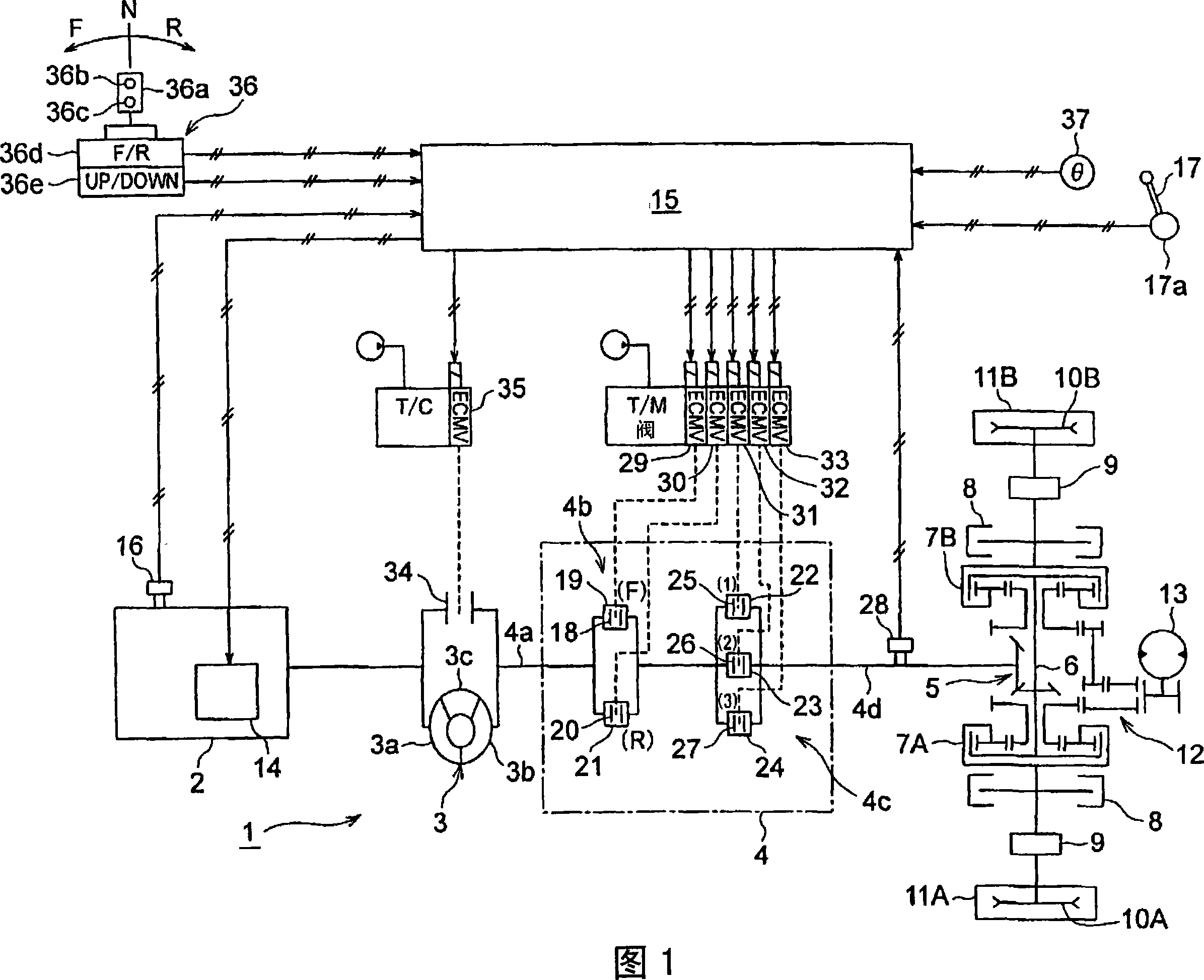
[0038] FIG. 1 is a configuration diagram of a shift control device 1 for a bulldozer according to an embodiment.

[0039] The configuration of the shift control device 1 shown in FIG. 1 will be schematically described.

[0040] In a construction vehicle such as a bulldozer, the output of the engine 2 is transmitted to drive wheels, ie, drive wheels 10A, 10B, through a power transmission path. A torque converter 3 , a lock-up clutch 34 that locks up the torque converter 3 , and a transmission 4 are provided in a power transmission path of the engine 2 . In the transmission 4, a forward clutch 18 corresponding to the forward driving gear 19, a reverse clutch 20 corresponding to the reverse driving gear 2...


PUM


Abstract

A shift control device and a shift control method for a vehicle capable of reducing shift shock by taking into account a difference between vehicle speeds before and after a shifting. In one of the main inventions, the clutch pressure of the other clutch (forward clutch) is controlled so that an actual vehicle speed calculated by a time when the engagement operation of a clutch for a selected speed stage is started matches a target vehicle speed. Since such a control that the vehicle speed is allowed to match the target vehicle speed is performed, an actual vehicle speed change rate comes within a specified range at least the instant that the engagement operation of the clutch for the selected stage is started. Also, in the other one of the main inventions, as shown in Fig. 7, the clutch pressure of the other clutch (forward clutch) is controlled so that the vehicle speed change rate becomes a specified value by a time when the engagement operation of the clutch for the selected speed stage is completed after the engagement operation is started.

Description

technical field [0001] The present invention relates to a vehicle speed change control device and a speed change control method suitable for being mounted on a construction vehicle such as a bulldozer. Background technique [0002] In construction vehicles such as bulldozers, the output power of the engine is transmitted to the drive wheels (drive wheels) through the power transmission path. In the power transmission path of the engine, a torque converter, a lock-up clutch that locks up the torque converter, and a transmission are provided. The transmission is provided with a forward clutch corresponding to a forward speed, a reverse clutch corresponding to a reverse speed, and speed clutches corresponding to each speed. A driving operation device is provided on the driver's seat of the engineering vehicle. The travel operating device is composed of a front and rear forward operating lever and a shift switch. It outputs forward operation instruction signal and reverse ope...

Claims


Application Information

Patent Timeline
Patent Type & Authority Applications(China)
IPC IPC(8): F16H61/06F16H59/44F16D48/02F16H59/66F16H61/14F16H61/682B60K31/00
CPCF16D2500/3108F16D2500/70406F16H61/143B60W30/20F16D2500/50684F16H2059/405F16H59/40F16D2500/30825F16H61/061F16D48/066F16D2500/1026F16H2061/145B60W2710/027F16H2306/54B60W2720/10F16D48/02F16D48/062F16D2500/10412F16D2500/1045F16D2500/1112F16D2500/30406F16D2500/3067F16D2500/3102F16D2500/3127F16D2500/3144F16D2500/3146F16D2500/50239F16D2500/7041F16D2500/70418F16D2500/70462
Inventor 中川智裕山本茂冈俊治冈田俊一
Owner KOMATSU LTD
Features
  • Generate Ideas
  • Intellectual Property
  • Life Sciences
  • Materials
  • Tech Scout
  • Unparalleled Data Quality
  • Higher Quality Content
  • 60% Fewer Hallucinations
Learn More