Supercharge Your Innovation With Domain-Expert AI Agents!

Separate moving templet structure of reaming type mould clamping mechanism

A moving formwork and separate technology, applied in the field of moving formwork, can solve the problems of ejector plate breakage, high clamping force, product flash phenomenon, etc., to achieve the effect of providing ejection position space, improving performance, and reducing mold deformation.

Active Publication Date: 2007-07-04
佛山市顺德区震德塑料机械有限公司
View PDF0 Cites 1 Cited by
  • Summary
  • Abstract
  • Description
  • Claims
  • Application Information

AI Technical Summary

Problems solved by technology

[0004] (1) The distribution of the clamping force F transmitted to the mold 10 is not uniform and reasonable; the force transmitted by the machine hinge to the movable platen 12 is borne by the upper and lower hinge ears 120, and the movable platen 12 is deformed after being stressed, and the deformation will Transfer to the mold, causing mold deformation, and the final phenomenon is that the product is prone to flashing, and requires high mold clamping force, which affects the service life of the mold
[0005] (2) The distribution of the ejection points on the ejector plate 11 is not reasonable enough
Therefore, it is often difficult to set up the ejector plate reasonably, resulting in unreasonable ejection force of the ejector plate and prone to breakage of the ejector plate.

Method used


Image

  • Separate moving templet structure of reaming type mould clamping mechanism
  • Separate moving templet structure of reaming type mould clamping mechanism
  • Separate moving templet structure of reaming type mould clamping mechanism

Examples


Embodiment Construction

[0019] The present invention will be further described below in conjunction with the accompanying drawings and embodiments.

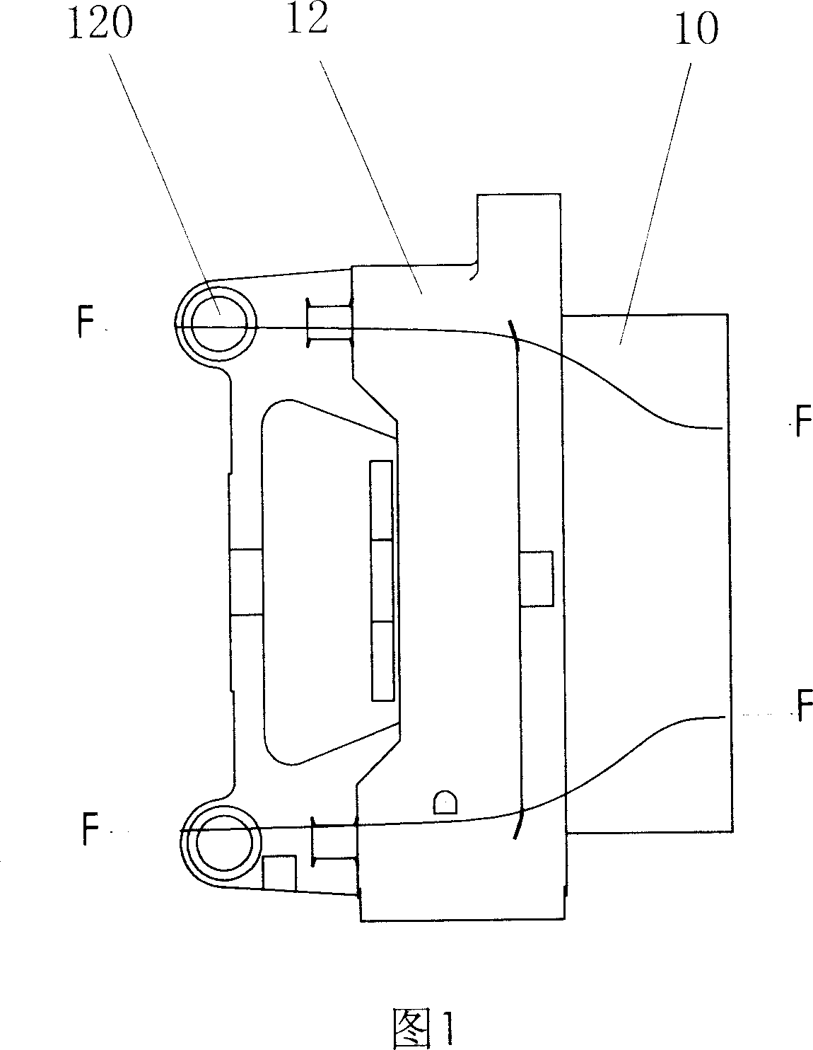
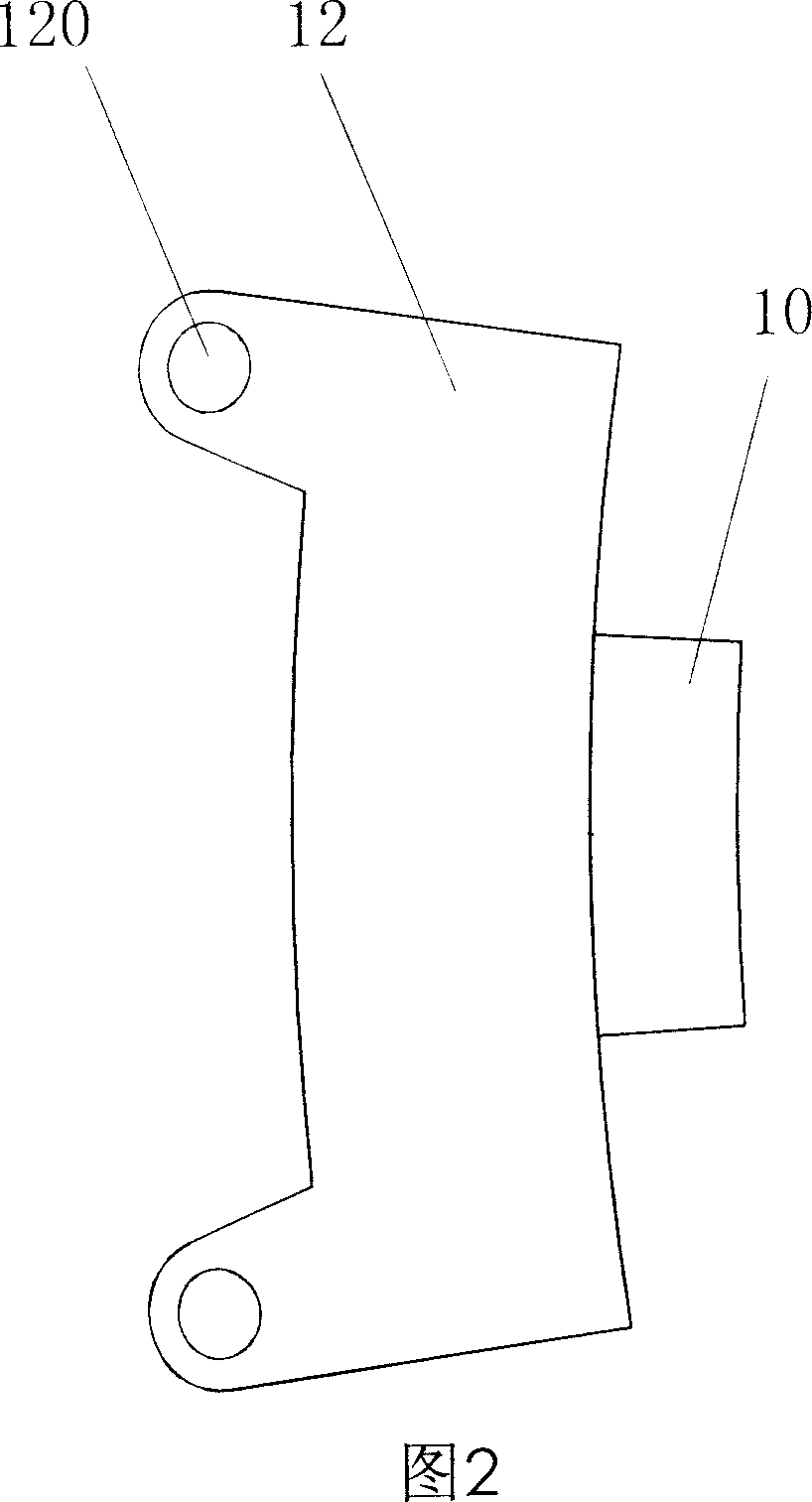
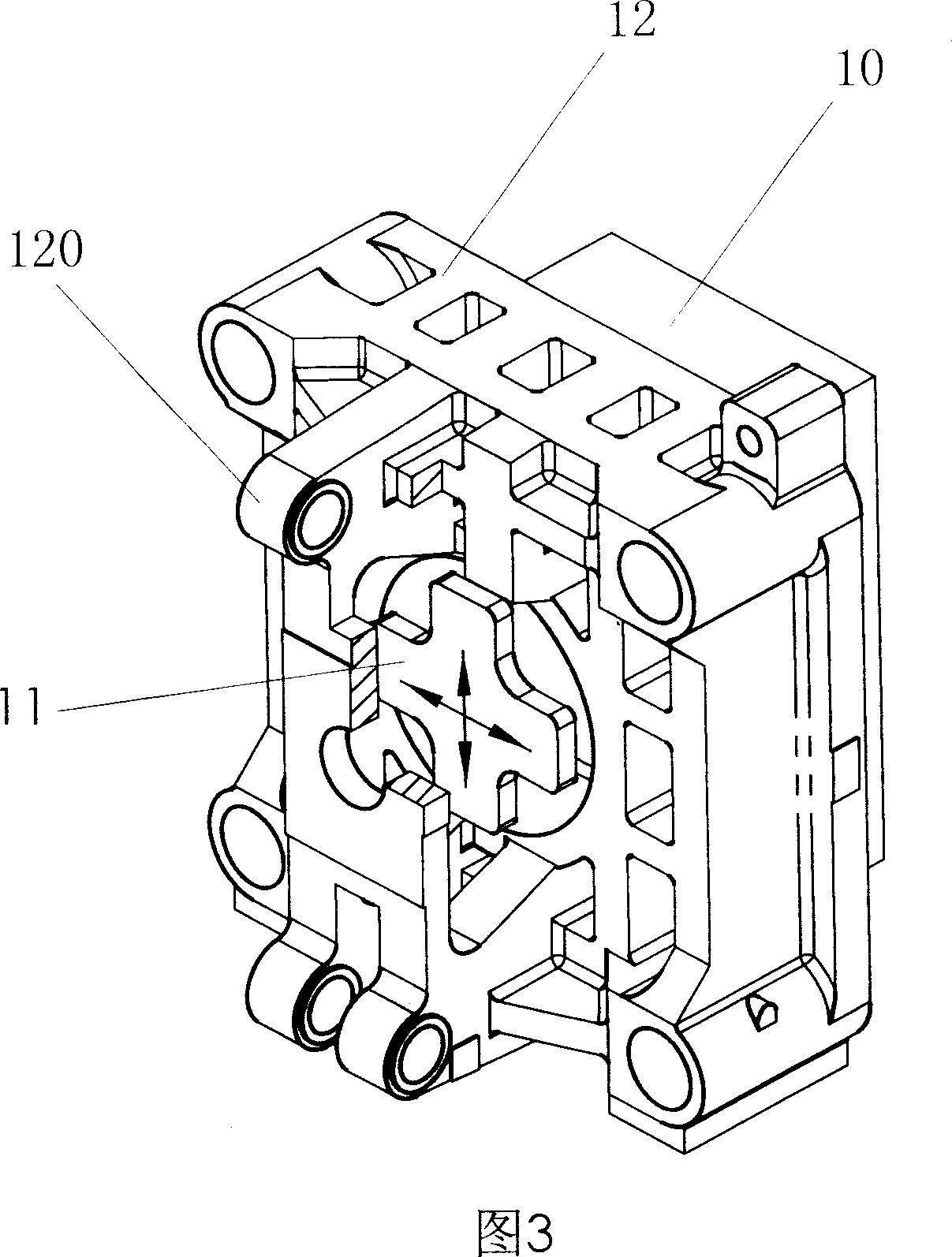
[0020] Referring to Fig. 4 to Fig. 7, the separated movable template structure of the hinged mold clamping mechanism is characterized in that it is provided with a front movable template 1 for installing the mold, a supporting block 2 and a rear movable template 3 connected to the hinge mechanism, and the supporting block 2 is arranged between the front moving template 1 and the rear moving template 3, and its two ends are offset against the front moving template 1 and the rear moving template 3 respectively. The front movable formwork 1, support block 2 and rear movable formwork 3 are integrally formed by casting or assembled from single parts.

[0021] There are four support blocks 2 in this embodiment, and the support blocks 2 are roughly evenly distributed along the center of the rear movable template 3 . The supporting block 2 is supported roughly...


PUM


Abstract

The invention discloses a separating typed mobile mould structure of hinged mechanism of casting shaping machine, front mobile mould with assembling die, bearing block and back mobile mould, wherein the bearing block is set between front and back mobile moulds with two ends resisting front and back mobile moulds; the separating typed mobile mould improves the force condition of board and mould, which reduces the deformation of mould effectively.

Description

Technical field [0001] The invention relates to a movable template of a mold clamping mechanism of an injection molding machine, in particular to a separated movable template structure of a hinged mold clamping mechanism. Background technique [0002] At present, conventional injection molding machine mechanical components are composed of injection mechanism, clamping mechanism and frame. In the most commonly used machine-hinged mold clamping mechanism, it is mainly composed of static platen, moving platen, tail plate and machine hinge mechanism. The mold is placed between the movable template and the static template. During the injection process, the movable template moves to the static template to close the cage and provide the mold force of the rubber in the cavity. The mold clamping force generally ranges from tens of tons to several thousand Tons vary. After the product is cooled in the mold cavity, the movable platen moves backward to open the mold, and then the prod...

Claims


Application Information

Patent Timeline
IPC IPC(8): B29C45/66B29C45/26B29C33/20
Inventor 谭树发张贤宝
Owner 佛山市顺德区震德塑料机械有限公司
Features
  • R&D
  • Intellectual Property
  • Life Sciences
  • Materials
  • Tech Scout
  • Unparalleled Data Quality
  • Higher Quality Content
  • 60% Fewer Hallucinations
Learn More