Antiswary bar with clamping band

A technology of stabilizer bars and clamps, applied in interconnection systems, suspensions, transportation and packaging, etc., can solve problems such as low efficiency, disconnection, and inability to achieve adjustable shrinkage, and achieve the effect of simple assembly

Inactive Publication Date: 2007-07-04
上海中星汽车悬架件有限公司
View PDF0 Cites 4 Cited by
  • Summary
  • Abstract
  • Description
  • Claims
  • Application Information

AI Technical Summary

Problems solved by technology

[0004] However, the stabilizer bar using the above-mentioned foldable locking ring mainly has the following disadvantages: 1) Since the ring is welded, sometimes if the welding point is not firm, it is prone to disconnection; 2) Since the position of the locking piece is fixed, it can only shrink 3) The work of assembling the locking ring to the stabilizer bar is cumbersome, time-consuming and inefficient; 4) The types of materials used for the locking ring are too complicated

Method used


Image

  • Antiswary bar with clamping band
  • Antiswary bar with clamping band
  • Antiswary bar with clamping band

Examples


Embodiment Construction

[0018] The present invention will be further described below with reference to the accompanying drawings and embodiments.

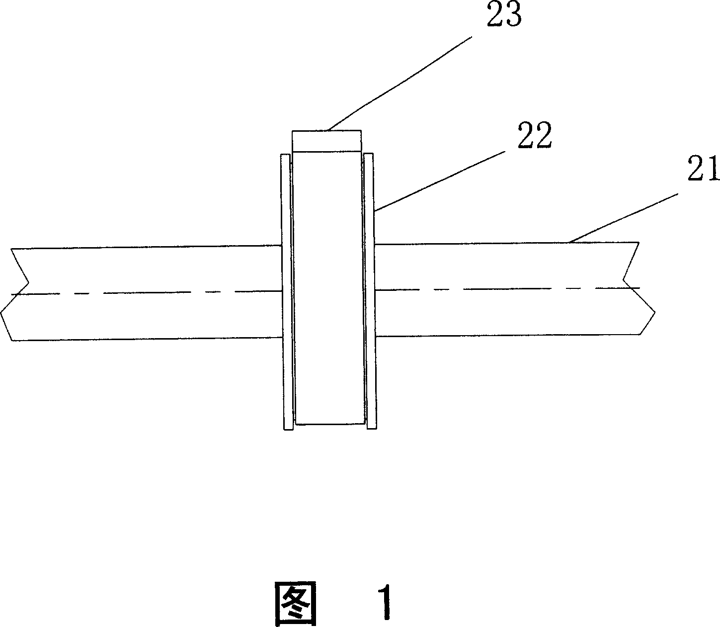
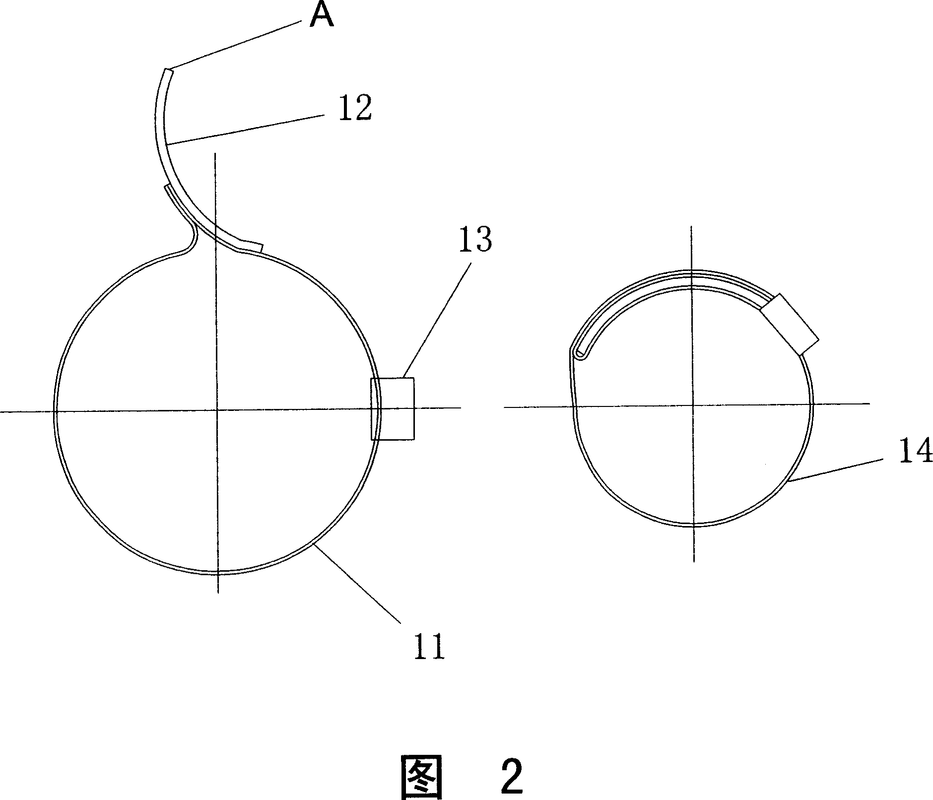
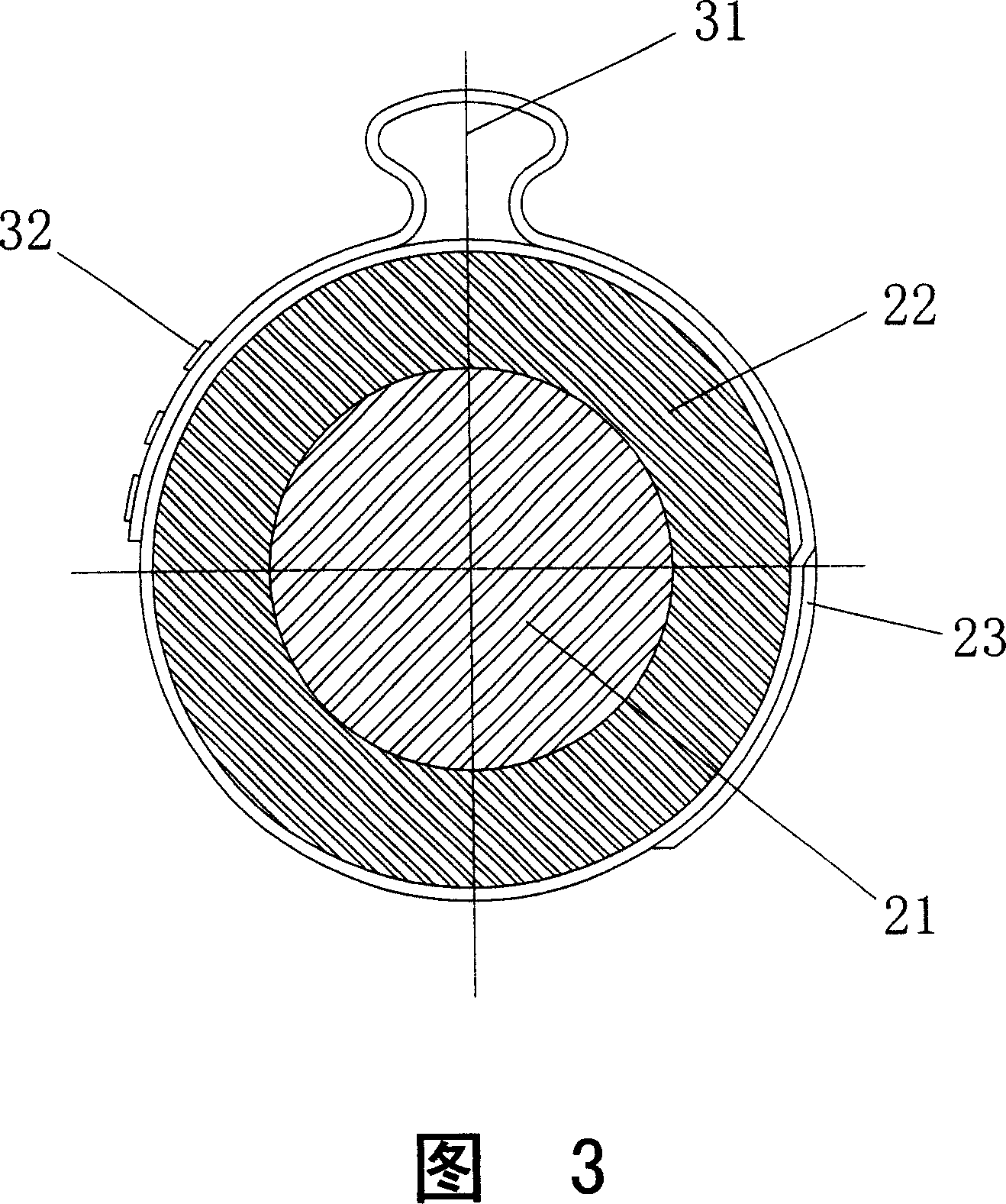
[0019] Figures 2 and 3 show the structure of the stabilizer bar with clamps. A limit ring 22 is sleeved on the body of the stabilizer bar 21 , the limit ring 22 is annular and made of rubber material, and its inner wall is closely attached to the stabilizer bar 21 . A single-eared stepless clamp 23 is arranged on the periphery of the limit ring 22 , and the clamp 23 is also annular with no steps and gaps on its inner surface, thereby ensuring that the entire inner surface is in close contact with the clamped limit ring 22 . Referring to FIG. 4 , the clamp 23 is made of stainless steel. The top of the clamp 23 has a boss 31 with an ear socket, so it is called a single ear. The clip 23 itself is connected by three raised blocks 32 .

[0020] When the clamp 23 needs to be locked, it is only necessary to tighten the top boss 31 with special calipers in the...


PUM


Abstract

The invention discloses a stable rod with clamp, which is characterized by the following: setting limit coil on the rod; assembling clamp on the exterior of limit coil; making clamp from single-ear non-polar clamp; fitting for making industry of automobile stable rod.

Description

technical field [0001] The invention relates to an automobile stabilizer bar, in particular to a stabilizer bar with a clamp. Background technique [0002] The stabilizer bar is an important part of the car chassis, which is usually used in combination with the subframe to provide the car with higher ride comfort and comfort. During the driving process of the car, the sudden start, emergency stop, steering and other operations of the car easily cause the lateral movement of the stabilizer bar, which leads to problems such as interference between the stabilizer bar and other parts of the frame or reduction of functions. In order to prevent the stabilizer bar from moving laterally, a limit ring is usually set on the stabilizer bar and the position where the frame is assembled. [0003] Generally, the limit ring is made of rubber material. After it is pasted to the surface of the stabilizer bar, it needs to be locked with a clamp on the periphery of the limit ring to prevent l...

Claims


Application Information

Patent Timeline
Patent Type & Authority Applications(China)
IPC IPC(8): B60G21/055
Inventor 马治祥
Owner 上海中星汽车悬架件有限公司
Why Eureka
Try Eureka