Display device, display system, method for controlling display device, and method for controlling electronic apparatus

a display device and display system technology, applied in the field of display devices, can solve the problems of difficult user grouping, complicated operation, and difficulty in understanding the identification code set of users, and achieve the effect of convenient grouping for users

Active Publication Date: 2018-06-19
SEIKO EPSON CORP
View PDF6 Cites 1 Cited by
  • Summary
  • Abstract
  • Description
  • Claims
  • Application Information

AI Technical Summary

Benefits of technology

[0008]An advantage of some aspects of the invention is that a technique for making it easier for the user to group a plurality of apparatuses connected via a network in a desired combination is provided.
[0016]According to the aspect of the invention with this configuration, since an input of group information associated with a physical button that is operated is accepted, the user can easily designate group information by an intuitive operation.
[0020]According to the aspect of the invention with this configuration, the user can easily group the display devices in a desired combination.

Problems solved by technology

The grouping of apparatuses may require the user to perform complicated operations.
However, in the case of the technique disclosed in JP-A-2010-258721, if there is a plurality of projectors, it is difficult for the user to understand which identification code is set to which projector.
In the case of the technique disclosed in JP-A-2007-43725, if there is a plurality of projectors displaying the same image, even when the user sees a preview image, it is difficult for the user to understand which projector image is shown by the preview image.
In the case of the technique disclosed in JP-A-2014-107713, even when the user sees the displayed IP address of a projector, it is difficult for the user to understand which IP address is allocated to which projector.

Method used


Image

  • Display device, display system, method for controlling display device, and method for controlling electronic apparatus
  • Display device, display system, method for controlling display device, and method for controlling electronic apparatus
  • Display device, display system, method for controlling display device, and method for controlling electronic apparatus

Examples


first embodiment

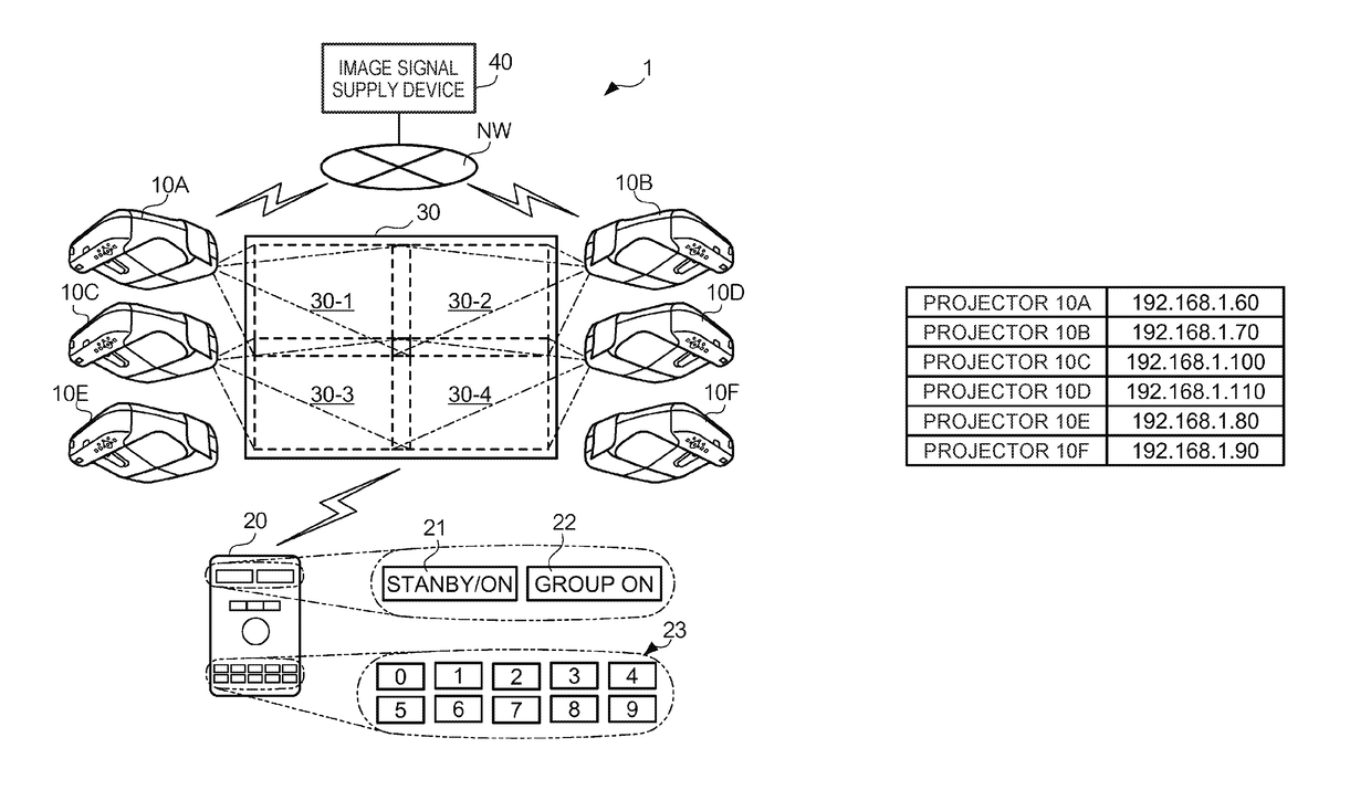
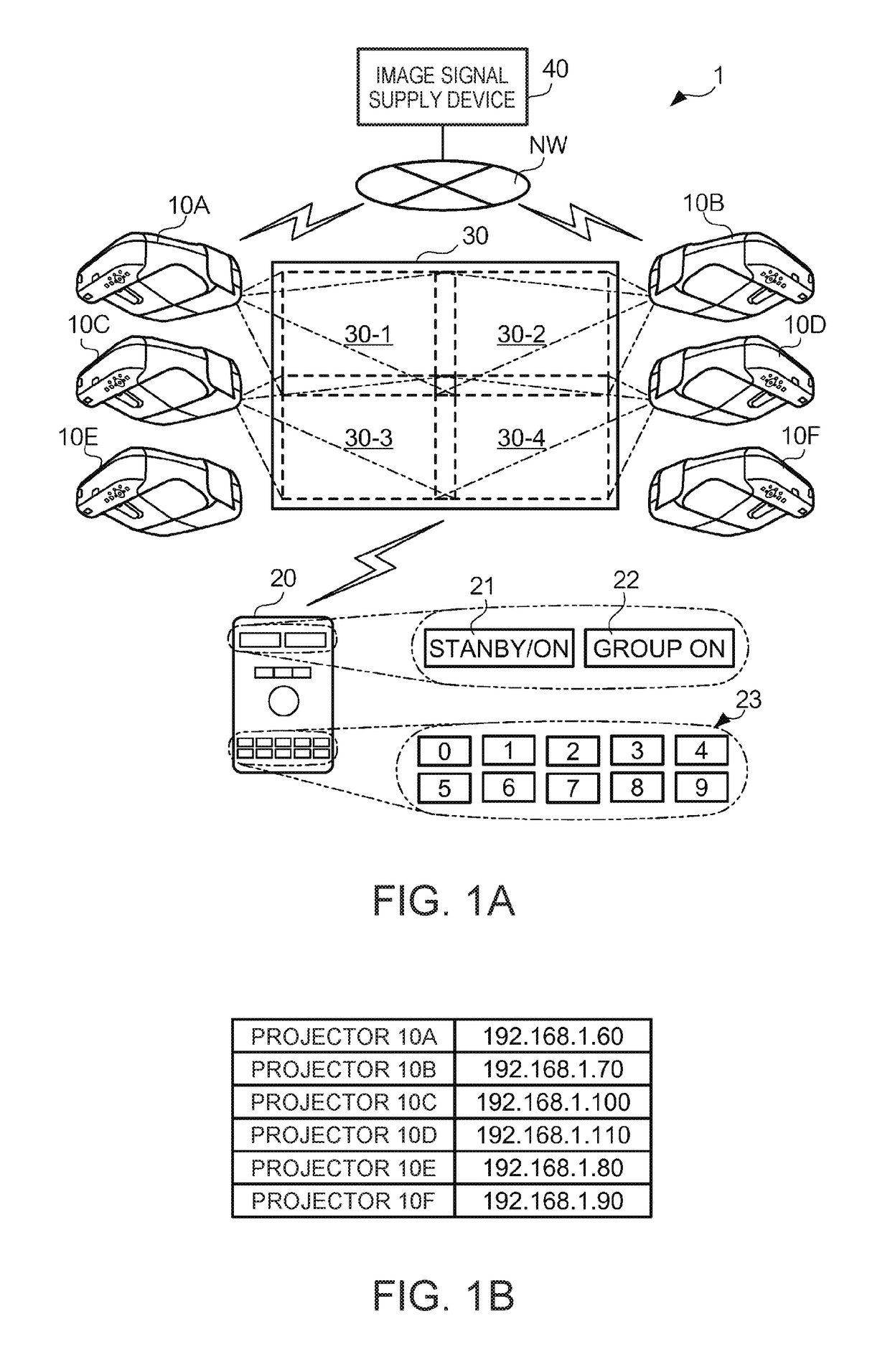
[0039]FIGS. 1A and 1B show the overall configuration of a projector system 1 according to a first embodiment of the invention. As shown in FIG. 1A, the projector system 1 is a display system including a plurality of projectors 10 (10A to 10F), a remote controller 20, and an image signal supply device 40. The projectors 10A to 10F in this example are arranged in the same room space and project an image on a screen 30. The remote controller 20 is used by the user in order to remotely control the plurality of projectors 10. The image signal supply device 40 is a personal computer, for example, and supplies an image signal for displaying an image (picture) on the screen 30, to each of the projectors 10A to 10F.

[0040]The projectors 10 are wall-mounted short throw projectors, for example, and are projection-type display devices which project an image on the screen 30 installed at a short distance. The projectors 10 project a color image based on an image signal corresponding to each color...

second embodiment

[0081]FIG. 8 shows the overall configuration of a projector system 2 according to a second embodiment of the invention. In this embodiment, the hardware circuits denoted by the same reference sings as those in the first embodiments are the same as the hardware circuits described in the first embodiment.

[0082]As shown in FIG. 8, the projector system 2 is a display system including projectors 10A to 10D, an image signal supply device 40, and a management device 50. The hardware configuration of each projector 10 may be the same as that in the first embodiment and therefore will not be described further in detail here. The IP addresses of the projectors 10A to 10D are the same as those in the first embodiment, as shown in FIG. 8.

[0083]The projectors 10A and 10B are arranged in a conference room R1, which is the same room space. The projectors 10C and 10D are arranged in a conference room R2, which is the same room space. Each of the projectors 10A to 10D can communicate via a network N...


PUM

PropertyMeasurementUnit
areaaaaaaaaaaa
areaaaaaaaaaaa
distanceaaaaaaaaaa

Abstract

A projector includes: an input accepting unit which accepts an input of first group information from a user; a receiving unit which receives, from each of other projectors connected via a network, second identification information for identifying these projectors, and second group information inputted to these projectors by the user; a generation unit which generates a selection screen for selecting a projector to be operated, first identification information for identifying the projector being associated with the first group information that is inputted in the screen, the second identification information being associated with the second group information in the screen; and a display unit which displays the selection screen that is generated.

Description

[0001]The entire disclosure of Japanese Patent Application No. 2015-145584, filed Jul. 23, 2015 is expressly incorporated by reference herein.BACKGROUND[0002]1. Technical Field[0003]The present invention relates to a technique for splitting a plurality of connected apparatuses into groups and controlling each group.[0004]2. Related Art[0005]A technique is known in which a plurality of apparatuses connected via a network is split into groups so that a predetermined function is utilized through a coordinated operation of two or more apparatuses classified as the same group. For example, in some cases, tiling projection in which partial images displayed by two or more projectors, respectively, are arranged next to each other on the same screen so as to display a picture (whole image), is carried out. The grouping of apparatuses may require the user to perform complicated operations.[0006]In this respect, JP-A-2010-258721 discloses a technique in which a projector transmits an identific...

Claims


Application Information

Patent Timeline
Patent Type & Authority Patents(United States)
IPC IPC(8): G06F1/00H04N9/31G09G3/00G06F3/14G06F3/041G06F3/0482G02F1/1333
CPCG06F3/1446G02F1/13338G06F3/0412G06F3/0416G06F3/0482H04N9/3147H04N9/3179H04N9/3194G09G3/001G09G2370/16G09G2300/026G09G2370/042G06F3/04842
Inventor KOSHIHASHI, TORU
Owner SEIKO EPSON CORP
Why Eureka
Try Eureka