Scanning device with overhead reflecting mirror

a scanning device and overhead reflection technology, applied in the field of scanning devices, can solve the problems of unnecessary image processing and complicated processing, and achieve the effect of facilitating the image processing of removing

Active Publication Date: 2018-06-19
AVISION
View PDF13 Cites 0 Cited by
  • Summary
  • Abstract
  • Description
  • Claims
  • Application Information

AI Technical Summary

Benefits of technology

[0006]Accordingly, the present invention has been proposed to solve the problems of the prior art, and an object of the present invention is to provide a scanning device with an overhead reflecting mirror for facilitating the image processing of removing a hole image or hole images from a scanned image obtained after a hole-containing document is scanned.
[0008]With the above-mentioned overhead reflecting mirror for reflecting the light penetrating through the hole of the original to the photosensor, the sensing cell of the photosensor reaches a saturated state to obtain a saturated value, which is significantly higher than the sensing value of the photosensor obtained when the light is reflected by a standard white pattern to the photosensor. The position of the hole can be determined according to the determined position of the saturated value, and the hole inpainting procedure can be performed. Thus, it is unnecessary to perform the complicated image processing to estimate the position of the hole. In addition, the control processing module can immediately determine and inpaint the hole image on one scan section according to the saturated value. Consequently, it is unnecessary to use a large-capacity memory and buffer as well as a high-performance processor, and the cost of the system resource can be saved. Thus, the cost of the scanning device or peripheral can be effectively decreased, and the scanning device or peripheral can also directly process the image inpainting and then output the inpainted image to a computer device connected thereto.

Problems solved by technology

Thus, it is unnecessary to perform the complicated image processing to estimate the position of the hole.

Method used


Image

  • Scanning device with overhead reflecting mirror
  • Scanning device with overhead reflecting mirror
  • Scanning device with overhead reflecting mirror

Examples


Embodiment Construction

[0017]The present invention will be apparent from the following detailed description, which proceeds with reference to accompanying drawings.

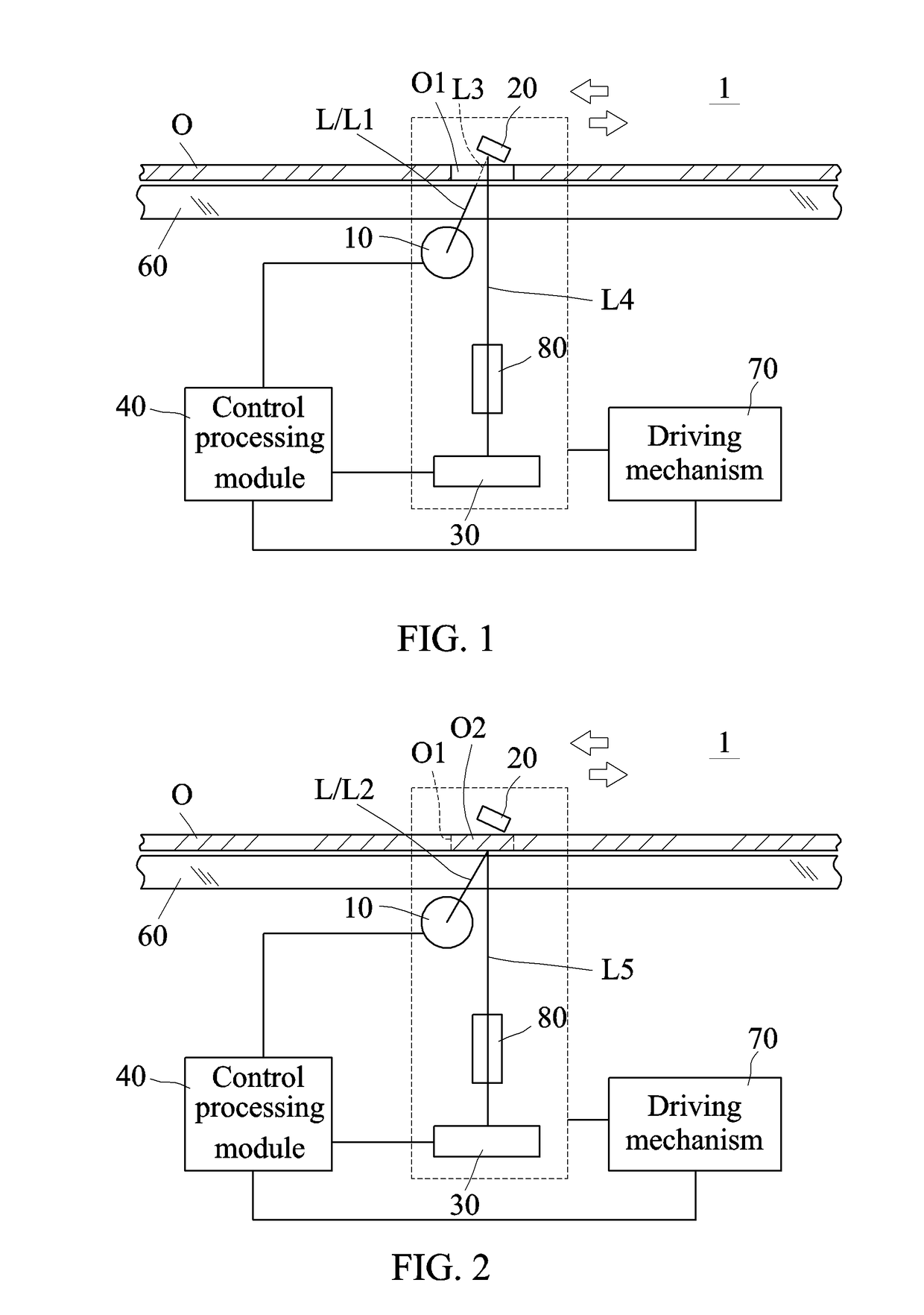
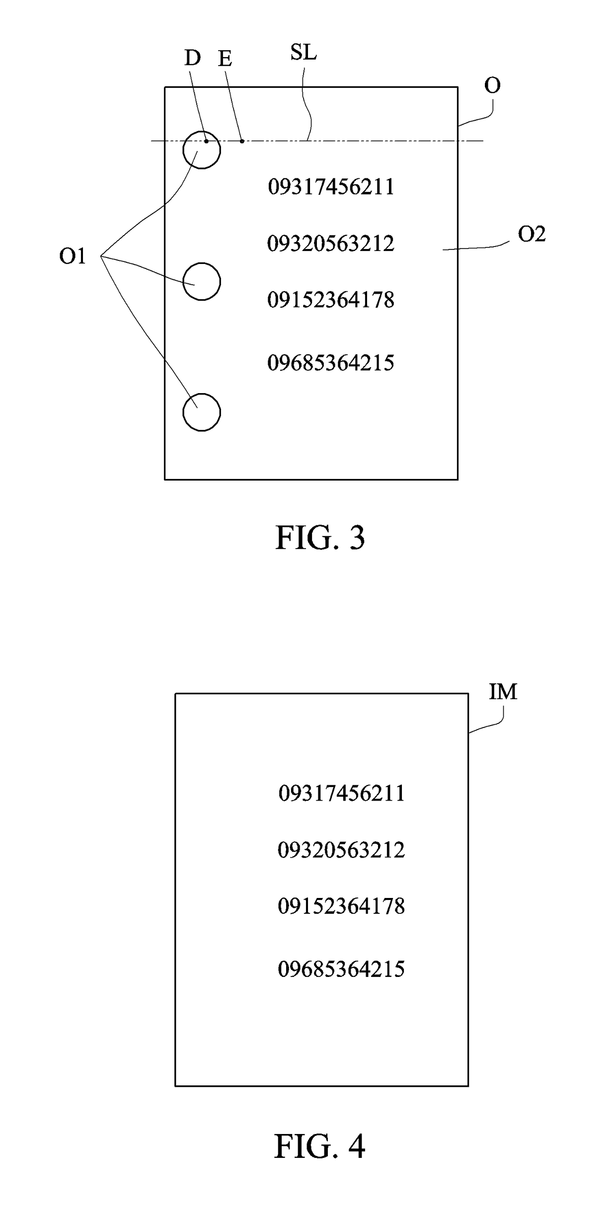
[0018]FIGS. 1 and 2 are schematic views showing two different states of a scanning device 1 according to a first embodiment of the present invention. FIG. 3 is a schematic view showing an original O. FIG. 4 is a schematic view showing a hole-free image representative of the original. The purpose of this embodiment is to scan the original O using the scanning device, and to process the image of the hole-containing original into the hole-free image using its own processing module or an externally connected processing module.

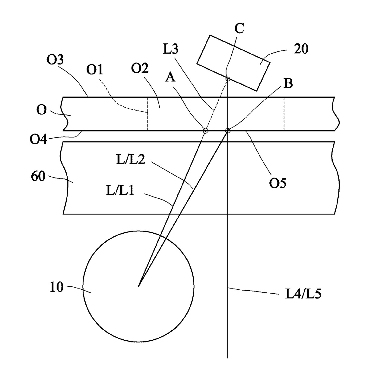
[0019]Referring to FIGS. 1 to 4, the scanning device 1 of this embodiment comprises a light source 10, a reflecting mirror 20 and a photosensor 30, all of which are disposed inside a housing (not shown) of the scanning device 1. In FIGS. 1 and 2, the light source 10, the reflecting mirror 20 and the photosensor 30 extend in a ...


PUM


Abstract

A scanning device comprises a light source, a reflecting mirror and a photosensor. The light source provides light to an original. A first portion of the light penetrates through a hole of the original and becomes penetrating light. A second portion of the light is reflected by a hole-free portion of the original and becomes second reflected light. The reflecting mirror reflects the penetrating light and generates first reflected light. The photosensor receives the first reflected light and the second reflected light and generates a hole-containing image signal representative of an image of the original.

Description

[0001]This application claims priority of No. 103143612 filed in Taiwan R.O.C. on Dec. 15, 2014 under 35 USC 119, the entire content of which is hereby incorporated by reference.BACKGROUND OF THE INVENTION[0002]Field of the Invention[0003]The present invention relates to a scanning device, and more particularly to a scanning device with an overhead reflecting mirror for facilitating image processing of removing a hole image of an original or a document being scanned.[0004]Related Art[0005]A conventional scanner can be used to scan a document with a hole or holes. However, after the visible light is incident to the hole, a visible light sensor of the scanner cannot receive the visible light from the hole. So, the scanned result is presented as a fully black image corresponding to the position of the hole. If the user prints the image, a lot of toners are wasted in printing the fully black hole image. Although the image processing software can be executed to remove the hole image, suc...

Claims


Application Information

Patent Timeline
Patent Type & Authority Patents(United States)
IPC IPC(8): H04N1/38H04N1/10H04N1/00
CPCH04N1/38H04N1/00018H04N1/00037H04N1/00084
Inventor SHENG, THOMASCHEN, YEN-CHENG
Owner AVISION
Why Eureka
Try Eureka