Forward compatible retrofitting roadway light fixtures via a universal adjustable L-bracket

a retrofitting and forward-compatible technology, applied in fixed installation, lighting and heating equipment, lighting support devices, etc., can solve the problems of inefficient lighting operating using power hungry, retrofit projects become stalled, etc., to prevent backward compatibility and prevent backward compatibility with halogen lighting

Inactive Publication Date: 2018-07-03
MART GARY K
View PDF4 Cites 0 Cited by
  • Summary
  • Abstract
  • Description
  • Claims
  • Application Information

AI Technical Summary

Benefits of technology

The present invention relates to a system, method, and apparatus for retrofitting roadway light fixtures using a universal adjustable L-bracket. The technical effects of the invention include the ability to forward-compatibly retrofit multiple types of light fixtures, preventing backwards compatibility, and the ability to illuminate an immediate area with a high-output LED array. The method also involves simple steps to remove and connect the LED array to the light fixture, with minimal disassembly required.

Problems solved by technology

Frequently these retrofit projects become stalled due to cost or time restraints, or are never started due to administration changes.
For example, since LED arrays are more costly than halogen, LED arrays may be utilized until budget cuts force cities to return to halogen lighting since the light fixtures can use cheaper halogen bulbs.
Consequently, inefficient lighting continue to operate using power hungry halogen lighting.

Method used


Image

  • Forward compatible retrofitting roadway light fixtures via a universal adjustable L-bracket
  • Forward compatible retrofitting roadway light fixtures via a universal adjustable L-bracket
  • Forward compatible retrofitting roadway light fixtures via a universal adjustable L-bracket

Examples


embodiment 110

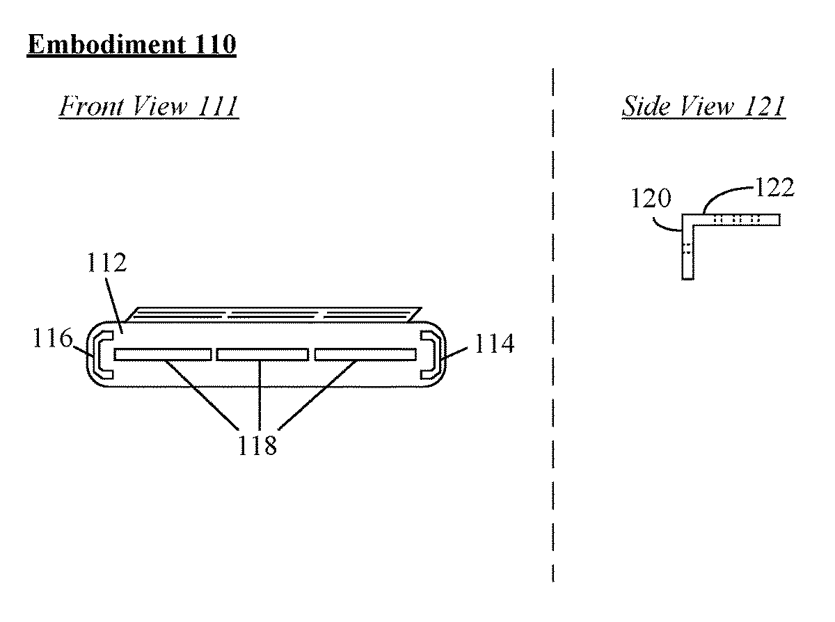
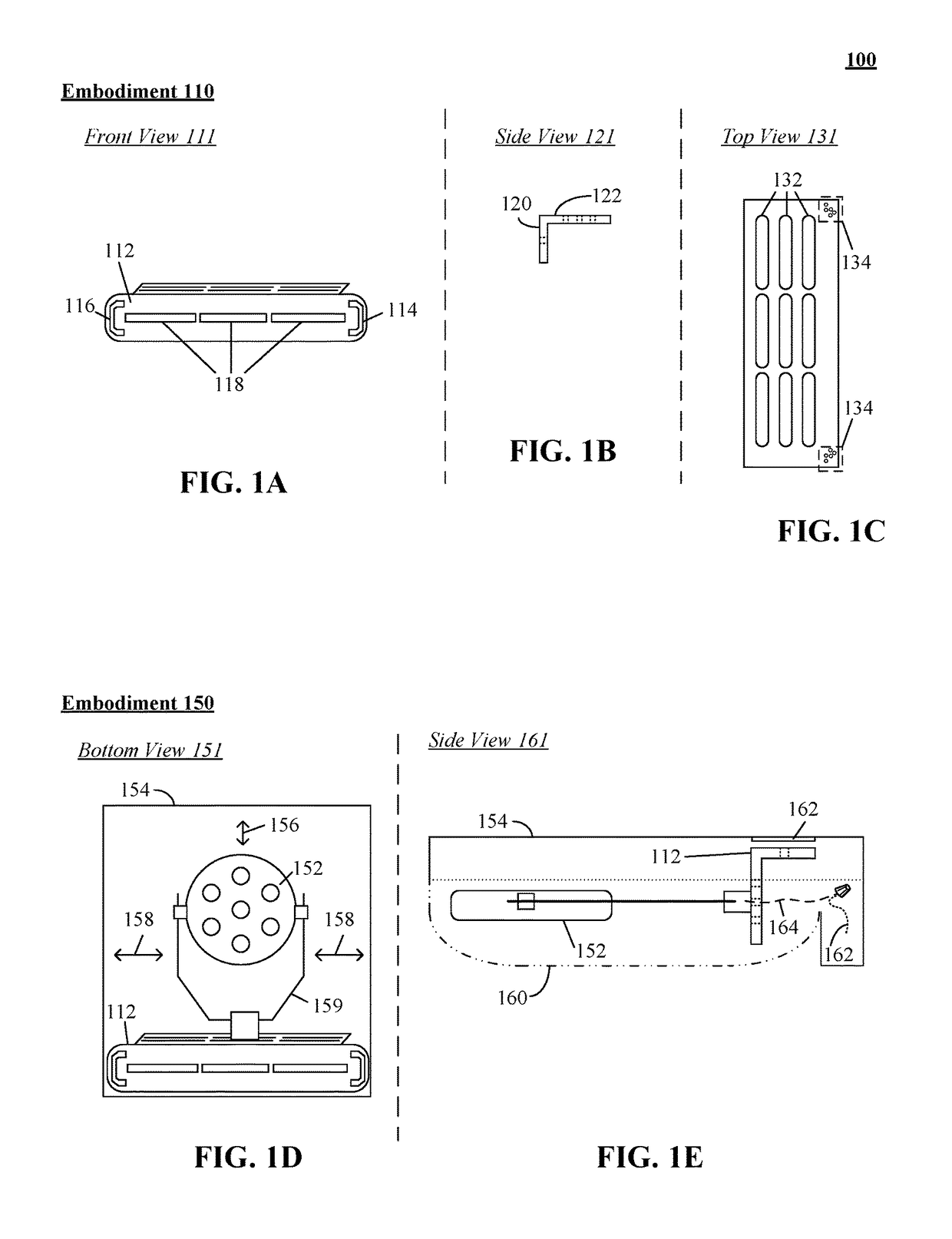
[0018]In embodiment 110, an L-bracket 112 can permit an LED array (e.g., 152) to be fitted into an existing light fixture (e.g., 154). L-bracket 112 can be an architectural element which can be structural or decorative. L-bracket 112 can include mount ends 114, 116, short end 120, long end 122, voids 118, 132, 134, and the like. Voids 118, 131, 134 can include, but is not limited to, one or more openings, one or more holes, and the like.

[0019]Front view 111 illustrates mount points 114, 116 located along the short end 120 with rectangular voids 118 within the center portion of short end 120. In one instance, short end 120 can be affixed to a mounting point 162 of light fixture 154. In the instance, mount ends 114, 116 can be utilized to position a positionable planar LED array 152 parallel to a ground surface to ensure lighting of an immediate area is performed.

[0020]In side view 121, short end 120 and long end 122 can be perpendicular forming an ‘L’ shape. In one embodiment, short ...

embodiment 150

[0023]In embodiment 150, a bottom view 151 can illustrate a positionable planar LED array 152 can be forward compatible retrofitted with array 152 using L-bracket 112. For example, fixture 154 can be a HOLOPHANE MONGOOSE light fixture which can be retrofitted with a planar LED array using L-bracket 112. In the view 151, array 152 position can be laterally adjusted 158 within an enclosure of fixture 154 by the sliding the base within a selected void 132 or changing void 132. In one instance, array 152 can be moved vertically within hood 160, by selecting a void 132 of bracket 112. It should be appreciated that LED array 152 can be adjustable permitting movement of array 152 within direction 156 via sliding array 152 along frame 159.

[0024]Side view 161 illustrates one embodiment for mounting planar LED 152 within a hood 160 of a light fixture. In one instance, an electrical lead 164 of planar LED 152 can be directly electrically connected to an exposed electrical lead 162. For example...

embodiment 310

[0040]In embodiment 310, an L-bracket 314 can include an extension plate 316 which can permit planar LED array 312 to be mounted within an enclosure as large as twenty-two point seven five inches and as small as eleven point seven five inches. In one embodiment, plate 316 can be affixed to bracket 314 via one or more voids within plate and bracket. In the embodiment, plate 316 can include a mount end similar to bracket 314. That is, extension plate 316 can permit planar LED array 312 to be mounted an any offset from eleven point seven five inches to twenty-two point seven five inches. In one instance, bracket dimensions can include a short end with a height of two inches and a length of eleven point seven five inches and a long end with a length of ten point two five inches and a width of four point five inches. In one embodiment, plate 316 can have a height of two inches and can be affixed to short end of bracket 314. It should be appreciated that planar LED array 312 can extend ni...


PUM


Abstract

A female lighting socket connector of a light fixture can be removed to expose electrical leads of the fixture. When an electric light is present within the female light socket, the electric light can be removed prior to removing the female lighting socket. A short end of a universal adjustable L-bracket can be affixed to a structural member of the light fixture. A positionable planar LED array can be attached to a long end of the bracket to place the LED in a forward facing position. The position can permit the light emitted from the LED to illuminate an immediate area. Electrical leads of the LED can be directly connected to the exposed electrical leads of the light fixture. The removal and connecting steps can prevent backwards compatibility. When the LED is connected to the fixture, the bracket and the LED can be substantially within an enclosure and / or a hood.

Description

BACKGROUND[0001]The present invention relates to the field of and roadway lighting, more particularly, to forward compatible retrofitting roadway light fixtures via a universal adjustable L-bracket.[0002]Roadway lighting such as halogen lamps used for lighting highways, sidewalks and public spaces (e.g., stadiums, parks) are energy intensive devices. In many instances, lighting can be required to be active for twelve or more hours (e.g., dusk to dawn), which can draw a considerable amount of electrical energy over this duration. To combat this energy inefficiency, government programs which provide incentives to cities and towns have been initiated. These programs offer credits and / or reduced rates for purchasing energy efficient components such as Light Emitting Diode arrays to retrofit roadway lighting. Frequently these retrofit projects become stalled due to cost or time restraints, or are never started due to administration changes. For example, since LED arrays are more costly t...

Claims


Application Information

Patent Timeline
IPC IPC(8): F21V19/02F21V21/14F21S8/08F21K9/237F21K9/235F21V3/00F21Y105/10F21Y115/10
CPCF21V21/14F21S8/086F21K9/237F21V19/02F21K9/235F21V3/00F21Y2105/10F21Y2115/10F21S8/08F21W2131/10F21W2131/103F21W2131/105F21K9/20Y02B20/30
Inventor MART, GARY K.
Owner MART GARY K
Why Eureka
Try Eureka