Duty-ratio controller

a controller and duty-ratio technology, applied in the direction of energy industry, efficient power electronics conversion, electric variable regulation, etc., can solve the problems of complex additional network, prone to noise, and negative influence on the harmonic distortion of input current, and achieve the effect of low cost hardware and simple design

a controller and duty-ratio technology, applied in the direction of energy industry, efficient power electronics conversion, electric variable regulation, etc., can solve the problems of complex additional network, prone to noise, and negative influence on the harmonic distortion of input current, and achieve the effect of low cost hardware and simple design

US10020724B2Active Publication Date: 2018-07-10DELTA ELECTRONICS (THAILAND) PUBLIC CO LTD

Image

  • Duty-ratio controller
  • Duty-ratio controller
  • Duty-ratio controller

Examples


Embodiment Construction

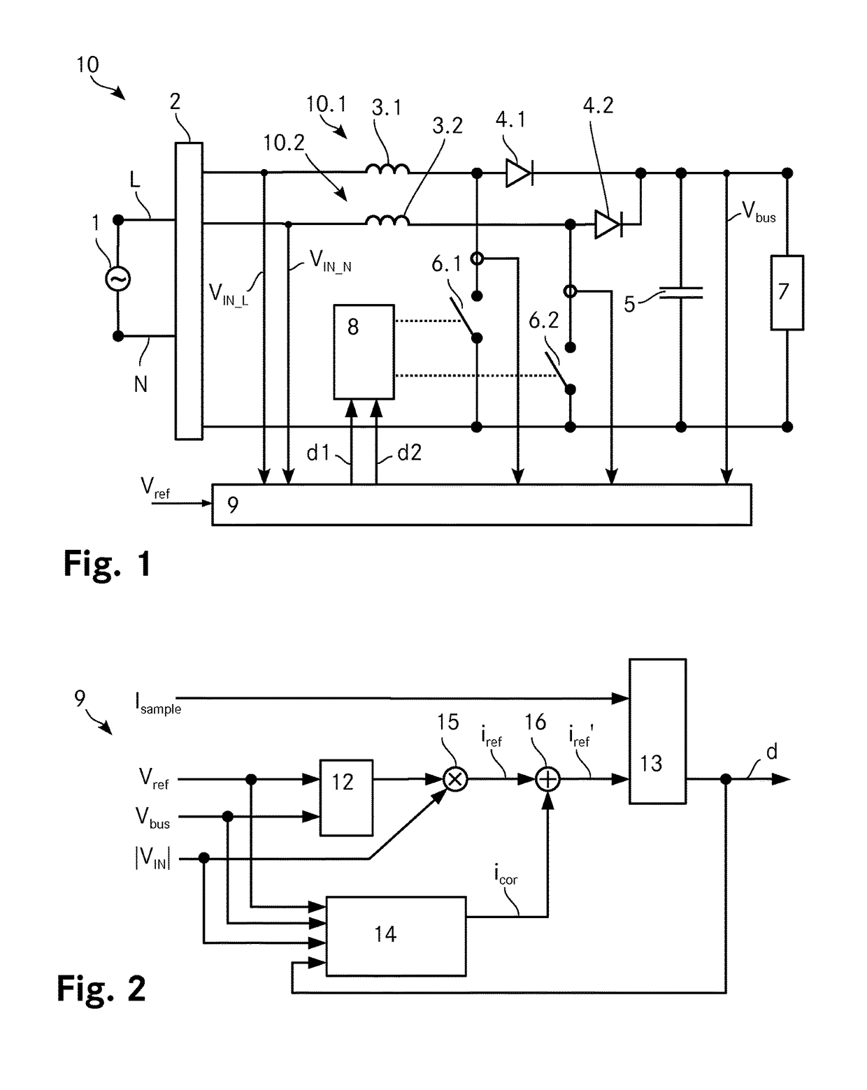
[0062]FIG. 1 shows a schematic depiction of a boost converter 10 according to the invention that includes two interleaved PFC converters. The boost converter 10 converts an AC input voltage to a DC output voltage. The two lines N (neutral line) and L (phase line) of the boost converter 10 are connected to an AC input source 1. At the input, the boost converter 10 includes an input stage 2, which includes a rectifier and for example an EMI (electromagnetic interference) filter. The rectifier is for example a bridge rectifier such as a full bridge diode rectifier or any other suitable rectifier that provides a DC voltage at the output of the input stage 2. The input stage 2 is followed by the two interleaved boost stages 10.1, 10.2 that are connected in parallel and the phases of which are shifted by about 180°.

[0063]Each boost stage 10.1, 10.2 includes a boost inductance 3.1, 3.2 connected to the input stage 2, followed by a boost diode 4.1, 4.2 where the anode of each boost diode 4....


PUM


Abstract

A controller for determining the duty-ratio for a pulse width modulator of a converter includes an inner current loop, an outer voltage loop and a multiplier with an input voltage feed forward to connect both loops. A prediction unit determines a correction signal icor that is added to the reference current iref by means of an adder and it further determines a sample correction signal to correct the current samples in the current loop. This error-controlled duty-ratio prediction with sample correction results in an improved total harmonic distortion as well as in an improved power factor of the converter.

Description

TECHNICAL FIELD[0001]The invention relates to a controller for determining a duty-ratio for a pulse width modulator of a switching power conversion device, including a voltage controller adapted to determine a voltage controller output based on a reference voltage and a voltage feedback signal from a power output of the switching power conversion device and a current controller adapted to determine the duty-ratio. The invention further relates to a method for determining a duty-ratio for a pulse width modulator of a switching power conversion device and a corresponding switching power conversion device.BACKGROUND ART[0002]Converters are usually used to convert electrical energy from one form to another. Converter topologies can for example be classified as boost, buck or buck-boost converters where all three topologies can be implemented as a DC to DC or an AC to DC converter. Unless otherwise mentioned, the terms boost converter, buck converter and buck-boost converter as used in t...

Claims


Application Information

Patent Timeline
10 Jul 2018
Publication
US10020724B2
IPC
H02M7/68; H02M3/156; H02M1/42; H02M1/00
CPC
H02M1/4208; H02M1/4225; H02M3/156; Y02P80/112; H02M2001/0025; Y02P80/10; H02M1/0025; Y02B70/10
Inventors
WEIDA, DANIEL; STAEHLI, MATTHIAS