Digital speaker, speaker system, and earphones

a speaker system and digital technology, applied in the field of digital speakers, can solve the problems of reducing sound quality, difficult miniaturization, and inability to realize enablement using the disclosed configuration, and achieve the effect of high sound quality and high sound quality

Active Publication Date: 2018-07-10
DAIICHI SEIKO CO LTD
View PDF11 Cites 0 Cited by
  • Summary
  • Abstract
  • Description
  • Claims
  • Application Information

AI Technical Summary

Benefits of technology

[0028]According to the present disclosure, a digital speaker can be provided that is miniaturized and has high sound quality. A miniaturized speaker system can be provided that includes the miniaturized digital speaker, and a high sound quality speaker system can be provided in earphones, which are a miniaturized device.

Problems solved by technology

However, due to speaker units using a permanent magnet and voice coil often being utilized conventionally as each of the sound generating devices, a problem occurs due to mutual induction between coils.
Further, differences between the individual coils also cause a problem of decreased sound quality.
Also miniaturization is difficult due to the requirement that the number of speakers matches the bit count.
However, Patent Literature 2 does not disclose a circuit applying a voltage to each of the electrodes, and enablement cannot be realized using the disclosed configuration.
Further, the voltage of each bit is applied separately to the central portion and circumferential portion of the piezoelectric element, and thus frequency characteristics of each bit in the piezoelectric element are not uniform.

Method used


Image

  • Digital speaker, speaker system, and earphones
  • Digital speaker, speaker system, and earphones
  • Digital speaker, speaker system, and earphones

Examples


embodiment 1

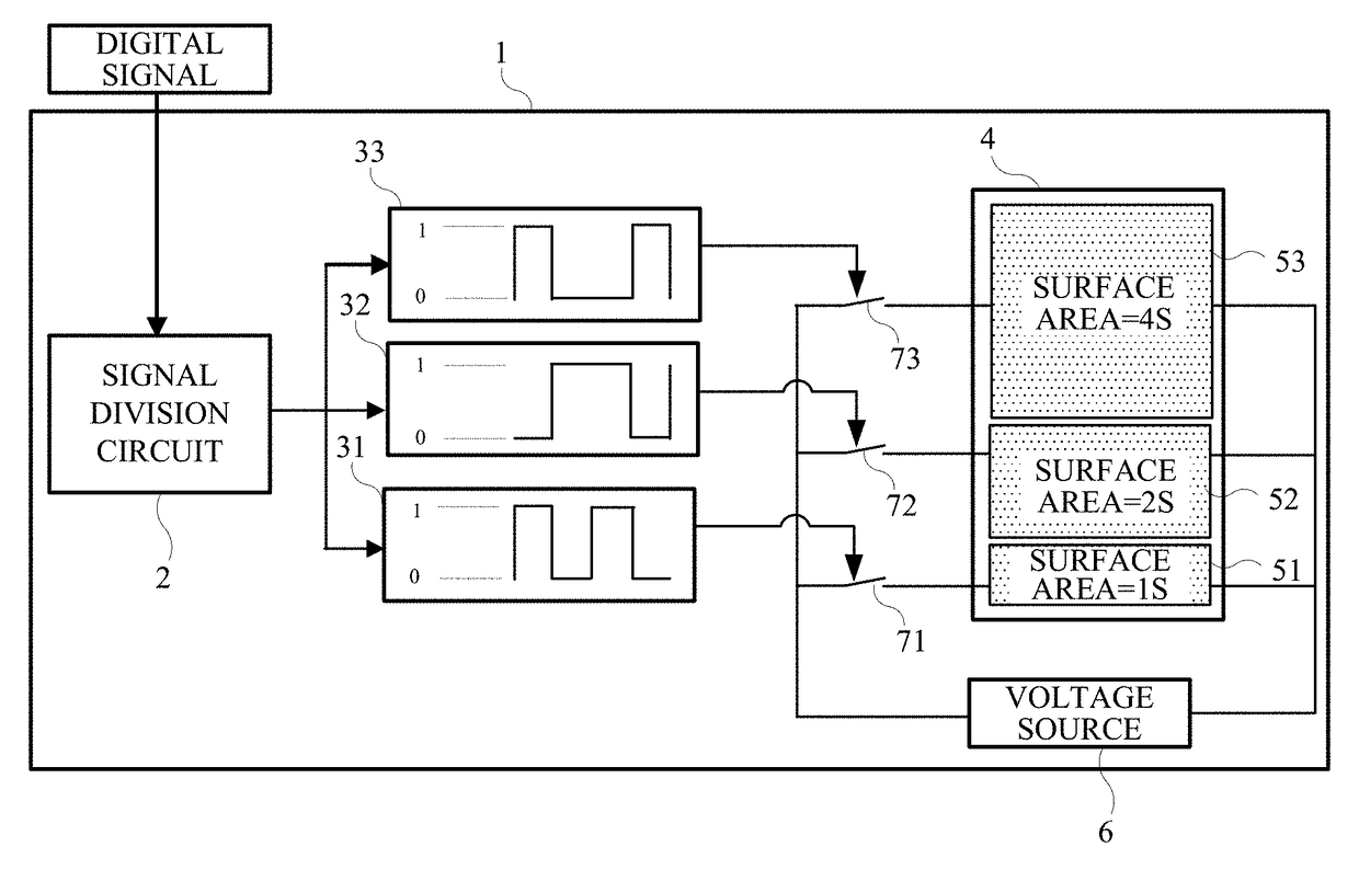
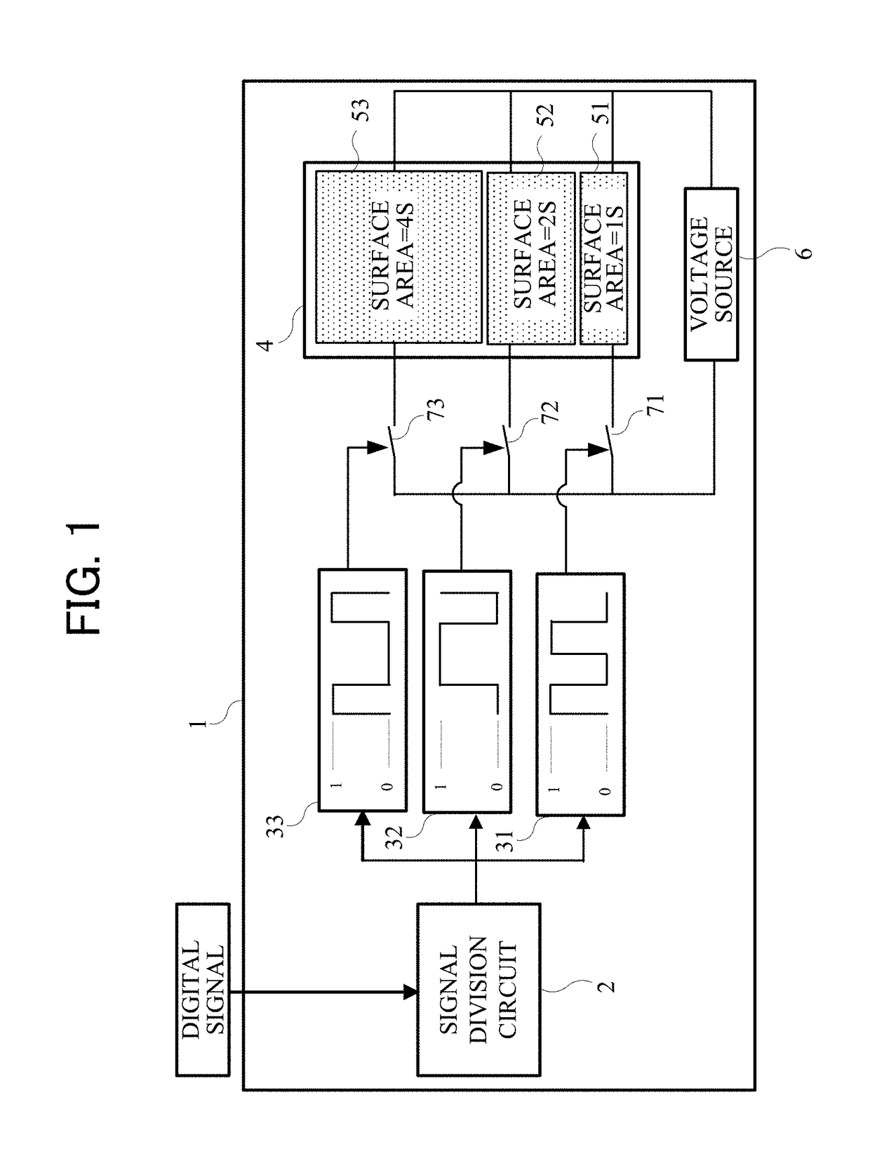
[0033]FIG. 1 is a drawing illustrating a configuration of a digital speaker 1. The digital speaker 1 includes a signal division circuit 2, a piezoelectric element 4, electrodes 51, 52, and 53, a voltage source 6, and switches 71, 72, and 73.

[0034]The signal division circuit 2 divides an inputted digital signal into bit units and generates post-division digital signals 31, 32, and 33. The post-division digital signal 31 is a signal indicating a lowest-order bit, the post-division digital signal 32 is a signal indicating a middle-order bit, and the post-division digital signal 33 is a signal indicating a highest-order bit. Although the digital signal in the present embodiment is taken to be a 3 bit signal, the digital signal may have 4 or more bits.

[0035]The piezoelectric element 4 converts voltage into force. The piezoelectric element 4, for example, is formed from a ceramic such as lead zirconate titanate (PZT) or the like. In practice, the piezoelectric element 4 is formed into a d...

embodiment 2

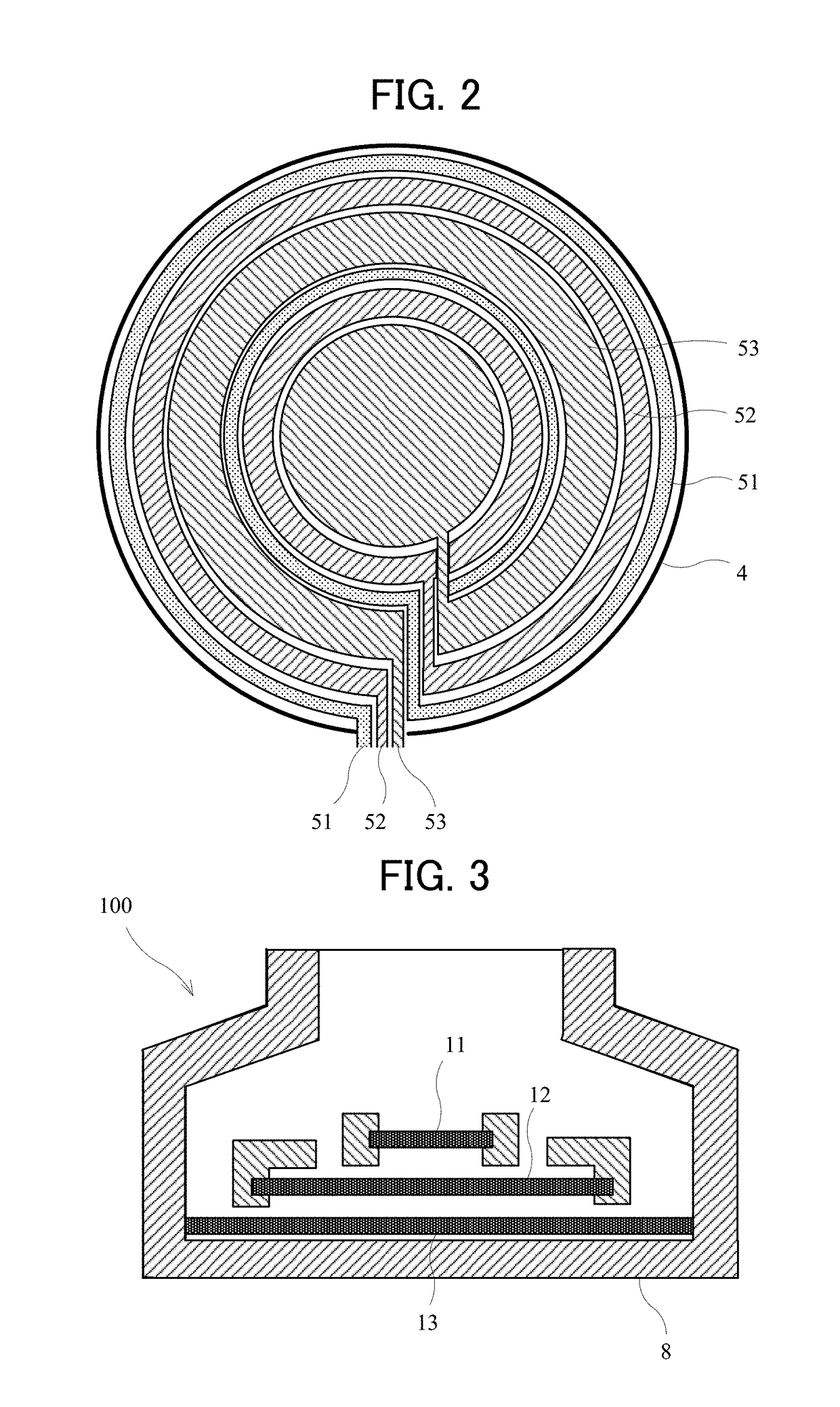
[0056]Embodiment 2 illustrates a speaker system including the digital speaker 1 of Embodiment 1, and illustrates earphones that include the speaker system. The digital speaker 1 (a tweeter 11, a squawker 12, and a woofer 13) is similar to Embodiment 1, and detailed description is omitted.

[0057]FIG. 3 is a drawing illustrating a configuration of a speaker system 100. The circumferential edges of the tweeter (speaker used for a high sound range) 11, the squawker (speaker used for a middle sound range) 12, and the woofer (speaker used for a low sound range) 13 that are the digital speakers 1 are supported by a frame 8. The frame 8 is molded in a cylindrical shape of constant wall thickness using a material such as metal or a resin. The piezoelectric element 4 supported by the frame 8 is disk-shaped and is illustrated in cross section in the figure. However, any desired shape may be used, such as a rectangle or an ellipse.

[0058]The voltage source 6, the signal division circuit 2, and th...


PUM


Abstract

A digital speaker (1) is provided that is equipped with a piezoelectric element (4) including n electrodes (51, 52, 53) spaced apart from one another. Sound pressure is adjusted according to the surface area of the electrodes (51, 52, 53), and all the electrodes (51, 52, 53) can be driven by the same voltage. A speaker system is provided that uses the digital speaker (1) as a tweeter (11), or as all the speakers including a woofer (13). By this speaker system, earphones (8) are provided that are miniaturized and have high sound quality.

Description

CROSS-REFERENCE TO RELATED APPLICATIONS[0001]This application is a U.S. National Phase of International Application No. PCT / JP2016 / 064630, filed on May 17, 2016, which claims the benefit of Japanese Patent Application No. 2015-102347, filed on May 20, 2015, including the specification, claims, and drawings, the entire disclosures of which is incorporated by reference herein.TECHNICAL FIELD[0002]The present disclosure relates to a digital speaker for generation of sound on the basis of a digital signal, a speaker system equipped with the digital speaker, and earphones equipped with the speaker system.BACKGROUND ART[0003]A digital speaker is known that generates sound on the basis of a digital signal (for example, see Patent Literature 1). The digital speaker can achieve high sound quality due to a lack of deterioration of sound quality by an analog system from audio amps and the like during transmission to the speaker. Further, for small-sized equipment such as mobile phones, the use...

Claims


Application Information

Patent Timeline
Patent Type & Authority Patents(United States)
IPC IPC(8): H04R1/10H04R17/00H04R3/12H04R1/24
CPCH04R1/1016H04R17/00H04R3/12H04R1/24H04R1/005H04R1/1075H04R1/26H04R19/02H04R2201/107H04R2205/022
Inventor OGATA, KENJIHOSAKA, AKIHIKOWATANABE, YOSHIYUKI
Owner DAIICHI SEIKO CO LTD
Why Eureka
Try Eureka