Mini-tube air cooled industrial steam condenser

a steam condenser and air-cooled technology, which is applied in the direction of indirect heat exchangers, refrigeration components, lighting and heating apparatus, etc., can solve the problems of not providing a means for removing non-condensable gases and saving expensive field welding labor, so as to reduce manufacturing costs, facilitate manufacturing, and be convenient to use

Active Publication Date: 2018-07-17
EVAPCO
View PDF8 Cites 6 Cited by
  • Summary
  • Abstract
  • Description
  • Claims
  • Application Information

AI Technical Summary

Benefits of technology

[0008]Turning to the new design for large scale field erected air cooled industrial steam condensers, a primary feature of this invention, is that the multiple primary and secondary condensers are arranged in a new design that reduces steam manifold costs and also increases the thermal capacity significantly at the same time allowing for easy containerized shipment and minimal field welding.
[0026]Additionally, the ACC design of the present invention can be sited more easily, requiring less overall space within the power plant.

Problems solved by technology

The first stage configuration is thermally efficient; however, it does not provide a means for removing non-condensable gases.
Another part of the logic is to weld the top steam manifold duct to each of the bundles at the factory and ship them together, thus saving expensive field welding labor.

Method used


Image

  • Mini-tube air cooled industrial steam condenser
  • Mini-tube air cooled industrial steam condenser
  • Mini-tube air cooled industrial steam condenser

Examples


Embodiment Construction

[0052]V-Shaped ACC with Horizontal Primary Condensers and Perpendicular Secondary Condensers

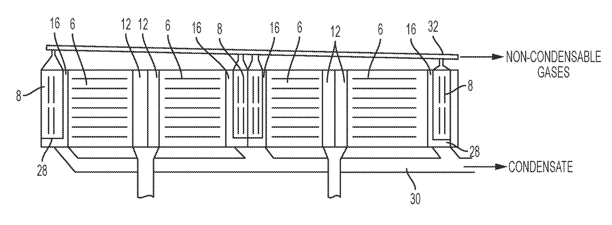
[0053]Referring FIGS. 2A, 2B, and 3, bundle pair 2 may be constructed by joining two bundles 4 in a V configuration. Each bundle 4 is constructed of four primary condensers 6 and four secondary condensers 8, each secondary condenser 8 paired with a single primary condenser 6. Tubes 10 in the primary condensers 6 are arranged such that the tubes 10 are horizontal, while the inlet steam manifolds 12 at one end of the tubes are aligned parallel to the transverse axis of the bundle. This arrangement allows the steam to enter the small inlet steam manifolds 12 from below. The tubes 14 in the secondary condenser 8 are likewise aligned parallel to the transverse axis of the bundle. The preferred vertical height of each bundle is 91 inches (2.3 m) to 101 inches (2.57 m) and the preferred bundle length is 38 ft to 45 ft.

[0054]According to a preferred embodiment, measuring along the length of the bundl...


PUM


Abstract

Large scale field erected air cooled industrial steam condenser having 10 heat exchanger bundles per cell arranged in five pairs in a V-shape, each heat exchanger bundle having four primary heat exchangers and four secondary heat exchangers in which each secondary heat exchanger is paired with a single primary heat exchanger. Four primary condensers are arranged such that the tubes are horizontal, while the inlet steam manifolds at one end of the tubes are perpendicular to the primary condenser tubes, i.e., parallel to the transverse axis of the bundle. Steam enters the small inlet steam manifolds from below. Cross-sectional dimensions of the tubes are 200 mm wide with a cross-section height of less than 10 mm with fins that are 10 mm in height, arranged at 9 to 12 fins per inch.

Description

BACKGROUND OF THE INVENTIONField of the Invention[0001]The present invention relates to large scale field erected air cooled industrial steam condensers.Description of the Background[0002]The current finned tube used in most large scale field erected air cooled industrial steam condensers (ACC) uses a flattened tube that is approximately 11 meters long by 200 mm wide (also referred to as “air travel length”) with semi-circular leading and trailing edges, and 18.7 mm external height (perpendicular to the air travel length). Tube wall thickness is 1.35 mm. Fins are brazed to both flat sides of each tube. The fins are usually 18.5 mm tall, spaced at 11 fins per inch. The fin surface has a wavy pattern to enhance heat transfer and help fin stiffness. The standard spacing between tubes, center to center, is 57.2 mm. The tubes themselves make up approximately one third of the cross sectional face area (perpendicular to the air flow direction); whereas the fins make up nearly two thirds of...

Claims


Application Information

Patent Timeline
Patent Type & Authority Patents(United States)
IPC IPC(8): B41D3/00F28B7/00F28B1/06F28D1/04
CPCF28B1/06F28B7/00F28D1/0426F28B2001/065F25B2339/04F28F1/02
Inventor BUGLER, TOMLIBERT, JEAN-PIERREHUBER, MARK
Owner EVAPCO
Why Eureka
Try Eureka