Display including electrowetting prism array

a technology of electrowetting prisms and arrays, applied in the field of display, can solve the problems of reducing the viewing distance, reducing the viewing angle, and reducing the refractive power of light emitted, and achieve the effect of increasing the refractive power of ligh

Active Publication Date: 2018-07-31
SAMSUNG ELECTRONICS CO LTD
View PDF12 Cites 2 Cited by
  • Summary
  • Abstract
  • Description
  • Claims
  • Application Information

AI Technical Summary

Benefits of technology

[0012]According to an aspect of an exemplary embodiment, a display including: a light source; a 2-dimensional (2D) display for providing an image using a light from the light source; a prism array for controlling a traveling direction of the image in real time; and an optical element for increasing refractive power of a light emitted from the prism array.

Problems solved by technology

That the contact angle of the prism included in the electrowetting prism array is limited to within the predetermined range denotes that beam steering of the electrowetting prism array is limited.
When the beam steering of the electrowetting prism array is limited, the refractive power or refraction ability of the electrowetting prism array is limited, the viewing angle and the viewing zone become limited or narrow, and reducing the viewing distance (the minimum distance capable of viewing a 3D image) may be limited.

Method used


Image

  • Display including electrowetting prism array
  • Display including electrowetting prism array
  • Display including electrowetting prism array

Examples


Embodiment Construction

[0036]Reference will now be made in detail to exemplary embodiments illustrated in the accompanying drawings, wherein like reference numerals refer to like elements throughout. In this regard, the present embodiments may have different forms and should not be construed as being limited to the descriptions set forth herein. Accordingly, the exemplary embodiments are merely described below, by referring to the figures, to explain aspects of the present description. In the drawings, the thicknesses of layers or regions are exaggerated for clarity.

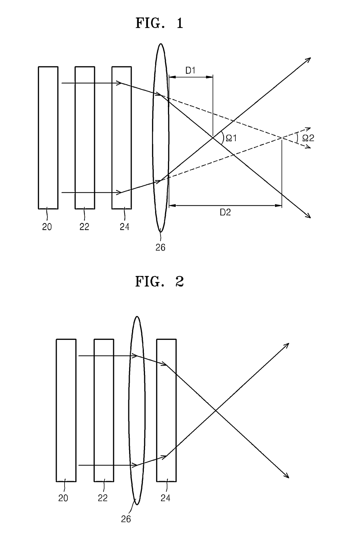
[0037]FIG. 1 is a cross-sectional view of a display (hereinafter, referred to as a first display) including an electrowetting prism array according to an exemplary embodiment.

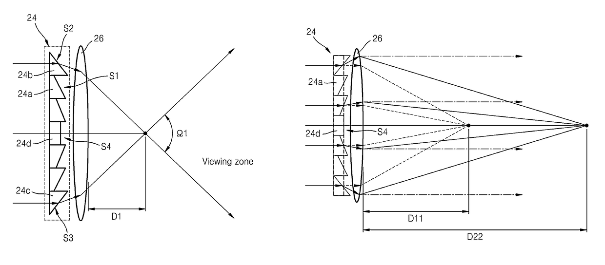
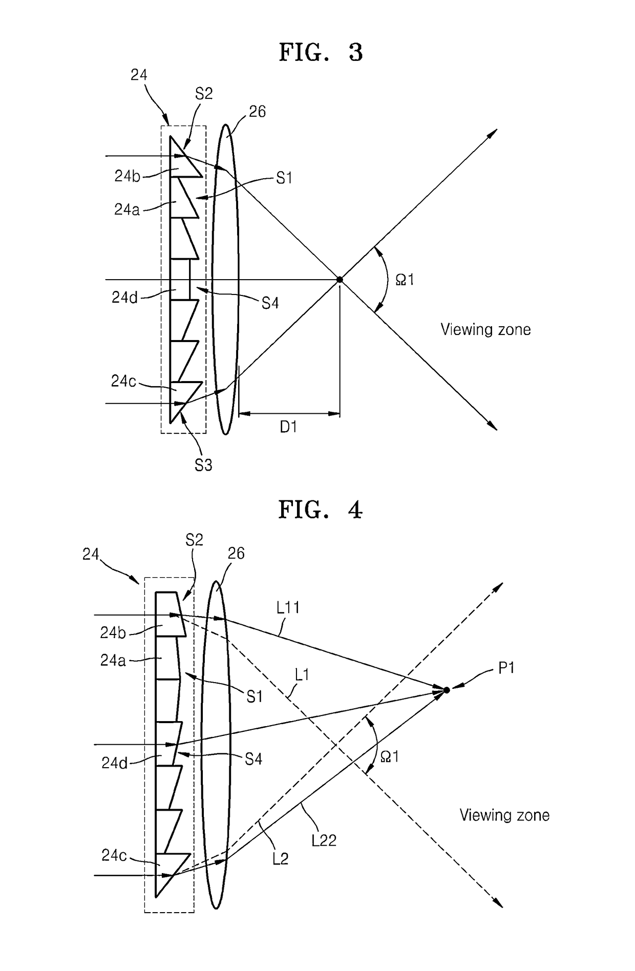
[0038]Referring to FIG. 1, the first display includes a light source 20, a liquid crystal panel 22 for creating an image, an electrowetting prism array (hereinafter, prism array) 24 for controlling a traveling direction of the image output from the liquid crystal panel 22...


PUM

PropertyMeasurementUnit
contact anglesaaaaaaaaaa
contact angleaaaaaaaaaa

Abstract

A display including an electrowetting prism array is provided. The display includes: a light source, a 2-dimensional (2D) display for providing an image using light from the light source, a prism array in which a refractive power of one or more prisms of the prism array is adjustable in real time, and an optical element which increases a refraction of light transmitted therethrough. In the display, the optical element may be disposed in front of or behind the prism array. The optical element may be a convex lens, a Fresnel lens, a holographic optical element (HOE), a diffraction optical element (DOE), or a second electrowetting prism array. The convex lens may be a variable focus lens.

Description

CROSS-REFERENCE TO RELATED APPLICATION[0001]This application claims priority from Korean Patent Application Nos. 10-2012-0148870, filed on Dec. 18, 2012, and 10-2013-0082296, filed on Jul. 12, 2013, in the Korean Intellectual Property Office, the disclosures of which are incorporated herein in their entirety by reference.BACKGROUND[0002]1. Field[0003]Apparatuses consistent with exemplary embodiments relate to a display, and more particularly, to a display including an electrowetting prism array and capable of converting 2-dimensional (2D) images to 3-dimensional (3D) images.[0004]2. Description of the Related Art[0005]Among technologies for displaying 3D videos, a technology using a binocular parallax separately provides two 2D images having binocular parallax to a left eye and a right eye. The two 2D images captured by a stereo camera approximate images acquired by the left and right eyes.[0006]Methods of observing a 3D image based on two 2D images includes methods using glasses an...

Claims


Application Information

Patent Timeline
Patent Type & Authority Patents(United States)
IPC IPC(8): G02F1/00G02B26/00G02B27/22
CPCG02B27/2242G02B26/005G02B30/36
Inventor KIM, YUN-HEESONG, HOONBAE, JUNG-MOKCHOI, KYU-HWANCHOI, YOON-SUNKWON, YONG-JOO
Owner SAMSUNG ELECTRONICS CO LTD
Why Eureka
Try Eureka