Variable lighting structure and endoscope

An illumination structure and variable technology, applied in the field of endoscopy, can solve the problems of unclear imaging, incomplete overlap between the illumination light field and the image field of view, and achieve the effect of compact overall structure and stable and reliable performance.

Inactive Publication Date: 2020-03-27
SHANGHAI AOHUA PHOTOELECTRICITY ENDOSCOPE
View PDF22 Cites 1 Cited by
  • Summary
  • Abstract
  • Description
  • Claims
  • Application Information

AI Technical Summary

Problems solved by technology

[0004] However, when the lighting structure on the existing side-viewing endoscope is used in practice, the illumination light field generated does not completely overlap with the image field of view, which leads to the fact that the non-overlapping part can only rely on diffuse reflection illumination during the operation, resulting in imaging Not clear

Method used


Image

  • Variable lighting structure and endoscope
  • Variable lighting structure and endoscope
  • Variable lighting structure and endoscope

Examples


Embodiment 1

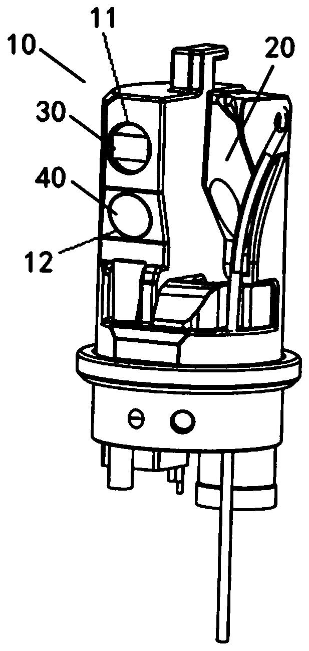
[0043] The endoscope described in this example is configured as a side-viewing endoscope (such as a duodenoscope, etc.), and the overall structure has an insertion part and an operation part. A universal cable is extended from the operation part, and the universal cable is connected to external equipment (such as a light source device, an image processor) through a connector, and finally the image is displayed on the display; at the same time, the insertion part has a front end, a bending part and flexible tubing. The specific composition scheme of this part is a well-known technology of those skilled in the art, and will not be repeated here.

[0044] In this example, an adjustable lighting structure is provided at the front end of the insertion part of the side-view endoscope to realize the adjustable lighting light field of the endoscope.

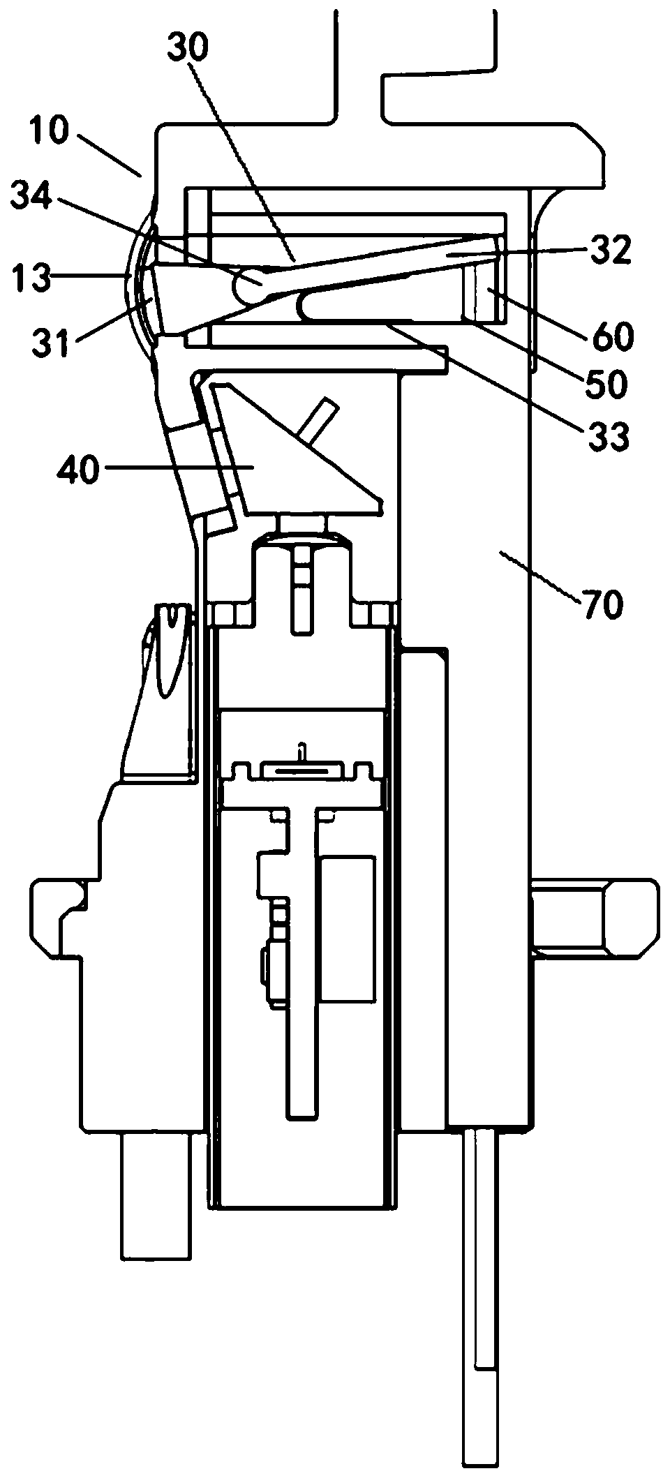
[0045] Here, the adjustable lighting structure is mainly composed of a lighting part, a transmission part and a light field adjustment...

Embodiment 2

[0089] Compared with the first embodiment, the present embodiment differs in the activity mode and structure of the lighting part, and the rest of the structures are the same, and the same parts will not be repeated here.

[0090] see Figure 9 with 10 , the lighting unit 90 in this example is mainly composed of an LED light source 91 , a support base 92 , an elastic member 93 and a rotating shaft 94 that cooperate with each other.

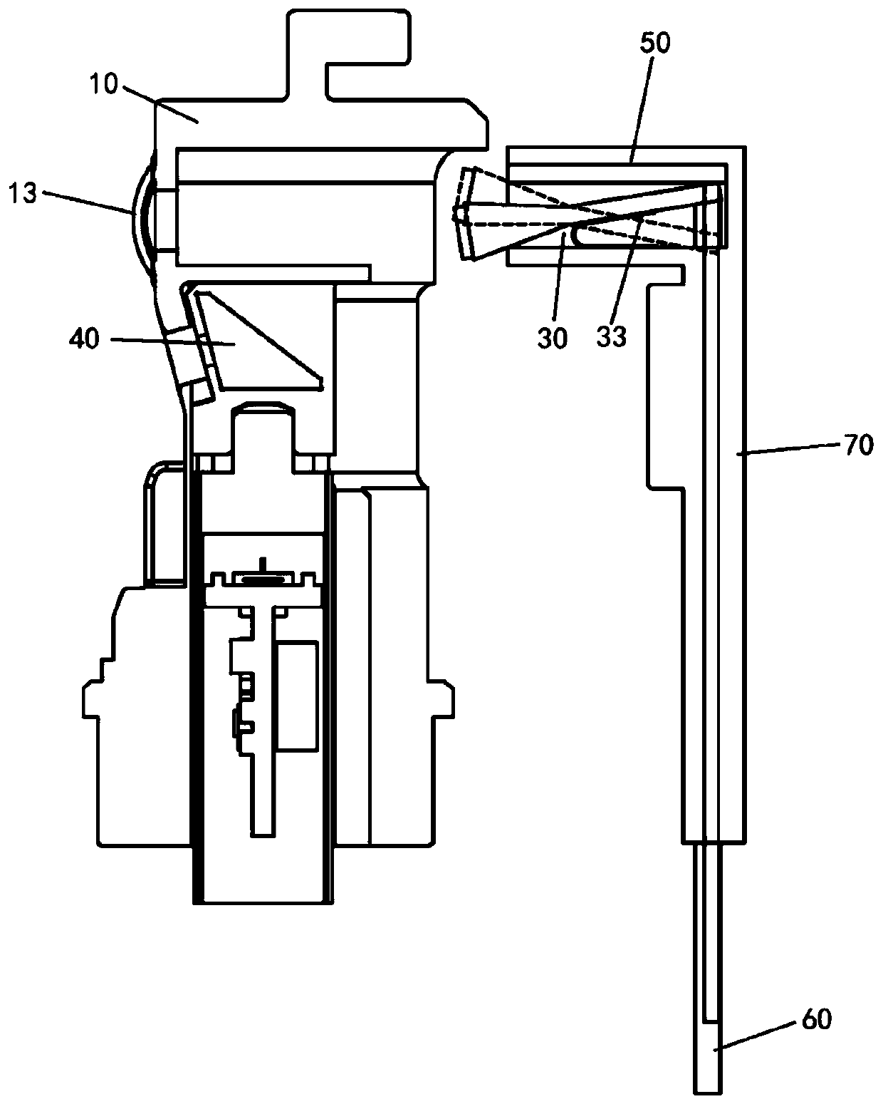
[0091] Concretely, this example is in the illumination part accommodating cavity (referring to image 3 A corresponding rotating shaft 94 is provided in the lighting part accommodation chamber 50), and the support seat 92 is integrally sleeved on the rotating shaft 94, and can rotate along the rotating shaft in the lighting part accommodation chamber under an applied force.

[0092] The top end surface of the support base 92 is used for disposing the LED light source 91 , and the bottom end is used for connecting the conducting part 60 . In ord...


PUM


Abstract

The invention discloses a variable lighting structure and an endoscope. According to the scheme, the variable lighting structure is formed through the cooperation of a lighting part, a transmission part and a light field adjusting part, wherein the lighting part can be movably arranged; the transmission part is in drive connection with the lighting part, and can drive the lighting part to move; the light field adjusting part is in drive connection with the transmission part; the light field adjusting part adjusts and controls the moving distance of the transmission part, the lighting part is driven by the transmission part to move, and then the area of a lighting field generated by the lighting part is adjusted. In the endoscope, it can be achieved that the direction of the lighting fieldand the lighting range are adjusted by using the variable lighting structure, an operator can adjust a lighting window according to actual operation conditions, and the problems are effectively solvedthat a visual lighting window and an image view field in an existing endoscope are incompletely overlapped, a non-overlapped part cannot be lighted in an surgical process, and unclear imaging can becaused only depending on reflected lighting.

Description

technical field [0001] The invention relates to an endoscope, in particular to the lighting technology of the front end of the endoscope. Background technique [0002] In recent years, endoscopes have gradually been widely used in the medical field. In endoscopes used in the medical field, in order to perform treatments such as treatment through the treatment instrument, some endoscopes are provided with a treatment instrument insertion channel through which the treatment instrument can be inserted. For example, a side-viewing endoscope used for ERCP (Endoscopic Retrograde Cholangio-Pancreatography: Endoscopic Retrograde Cholangio-Pancreatography) or the like has a treatment instrument lifting table at the front end for changing the protruding direction of the treatment instrument. [0003] For this type of side-looking endoscope, there is a big difference compared with ordinary front-looking endoscopes, and it has specific requirements for the illumination light field to m...

Claims


Application Information

Patent Timeline
Patent Type & Authority Applications(China)
IPC IPC(8): A61B1/06A61B1/273
CPCA61B1/0684A61B1/273A61B1/00071
Inventor 王燕涛
Owner SHANGHAI AOHUA PHOTOELECTRICITY ENDOSCOPE
Why Eureka
Try Eureka