Conductive liquid three dimensional printer

a three-dimensional printer and conductive liquid technology, applied in the direction of additive manufacturing, process efficiency improvement, additive manufacturing apparatus, etc., can solve the problems of high cost, risk of leakage, and easy wear and failure of moving parts, and achieve the effect of less expensive construction

Active Publication Date: 2018-08-07
ALLOY ACQUISITION CORP LLC
View PDF16 Cites 14 Cited by
  • Summary
  • Abstract
  • Description
  • Claims
  • Application Information

AI Technical Summary

Benefits of technology

[0012]The present disclosure overcomes the disadvantages of the related art. The present disclosure describes the application of a single pulse of direct current to an electromagnetic coil to create a radial force on a liquid conductive material. This radial force results in a drop of liquid conductive material being expelled from a nozzle onto a platform. As the platform moves relative to the nozzle, a series of drops solidify on the platform to form a 3D object. The present disclosure describes a device that will not corrode or arc like related devices. Further, the device of the present disclosure requires fewer moving parts and is less expensive to build than currently existing related devices.

Problems solved by technology

Three-dimensional printing of metal objects has been limited in its usefulness due to the technical difficulties in working with liquid metal.
With regard to the relevant art described previously, where mechanical force is used to generate a drop, seals and moving parts are prone to wear and failure.
This complexity adds friction, risk of leakage, low performance and more expensive maintenance requirements.
Similarly, mechanical means of displacing a drop generally involve more moving parts, which can lead to greater wear on the device and greater expense.
Such methods have not been effective enough to produce an economically viable liquid metal jet printer in the marketplace.
With the use of alternating current applied to a magnetic coil, the current must be applied in one direction and then the magnetic field must be reversed, a stepwise process that requires significant time, in terms of drop-on-demand printing and more complex and expensive power electronics.
While related devices have addressed this issue, none have been successful in limiting exposure of critical parts to corrosive liquid metal which subjects such devices to significant and expensive wear.

Method used


Image

  • Conductive liquid three dimensional printer
  • Conductive liquid three dimensional printer
  • Conductive liquid three dimensional printer

Examples


Embodiment Construction

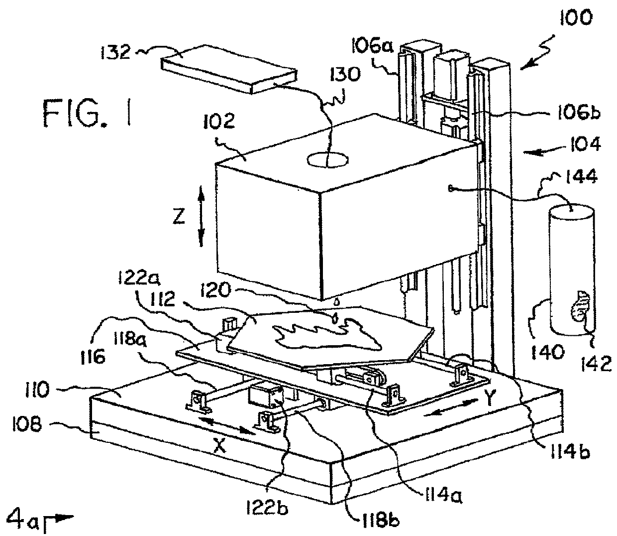
[0026]The following detailed description is merely exemplary in nature and is not intended to limit the described embodiments or the application and uses of the described embodiments. As used herein, the word “exemplary” or “illustrative” means “serving as an example, instance, or illustration.” Any implementation described herein as “exemplary” or “illustrative” is not necessarily to be construed as preferred or advantageous over other implementations. All of the implementations described below are exemplary implementations provided to enable persons skilled in the art to make or use the embodiments of the disclosure and are not intended to limit the scope of the disclosure, which is defined by the claims. For purposes of description herein, the terms “upper,”“lower,”“left,”“rear,”“right,”“front,”“vertical,”“horizontal,” and derivatives thereof shall relate to the invention as oriented in FIG. 1. Furthermore, there is no intention to be bound by any expressed or implied theory pres...


PUM

PropertyMeasurementUnit
melting pointaaaaaaaaaa
conductiveaaaaaaaaaa
electromotive forceaaaaaaaaaa

Abstract

A printer that produces objects from liquid conductive material is disclosed. In one embodiment, the print head has a chamber for containing liquid conductive material surrounded by an electromagnetic coil. A DC pulse is applied to the electromagnetic coil, resulting in a radially-inward force on the liquid conductive material. The force on the liquid conductive material in the chamber results in a drop being expelled from an orifice. In response to a series of pulses, a series of drops fall onto a platform in a programmed pattern, resulting in the formation of an object.

Description

[0001]This application is a continuation of U.S. patent application Ser. No. 14 / 228,681 filed on Mar. 28, 2014.FIELD OF THE INVENTION[0002]Liquid metal jet printing is, in one embodiment, a type of drop-on-demand printing. It is similar to ink-jet printing in that a drop of liquid to be printed is dispensed from a nozzle at specific intervals to create a figure or object. Typically, a platform beneath the nozzle moves in a pre-programmed pattern to form an object. To produce a pattern on the printing surface, drops are successively ejected from the nozzle after each movement of a printhead. The timing of the movement of the nozzle is often dependent upon the time required to produce a drop of liquid.BACKGROUND OF THE INVENTION[0003]In three-dimensional printing, patterns are generally repeated on a printing surface, where successive drops on top of another eventually produce a three-dimensional object. Three dimensional printing has been most successful, to this point, in creating p...

Claims


Application Information

Patent Timeline
Patent Type & Authority Patents(United States)
IPC IPC(8): B22D23/00B22D21/00B33Y10/00B33Y30/00
CPCB22D23/003B33Y30/00B33Y10/00B22D21/007B22F2999/00B22F10/22B22F12/10B22F12/53Y02P10/25B22F2202/05
Inventor VADER, SCOTTVADER, ZACHARY
Owner ALLOY ACQUISITION CORP LLC
Why Eureka
Try Eureka