Testing device for model of floating gate and method of using the same

a testing device and floating gate technology, applied in hydrodynamic testing, instrumentation, vessel construction, etc., can solve the problem that the hydrodynamic parameters of a floating gate model cannot be measured in a towing tank

Active Publication Date: 2018-08-07
DALIAN UNIV OF TECH
View PDF7 Cites 8 Cited by
  • Summary
  • Abstract
  • Description
  • Claims
  • Application Information

AI Technical Summary

Benefits of technology

[0020]5) allowing the model of a floating gate to float below the moon pool of the towing carriage, and connecting the model of a floating gate to the inner sleeve of the guide rod mechanism;
[0025]The testing device for a model of a floating gate of the disclosure has the following advantages. In this testing device for a model of a floating gate, the towing carriage is disposed on the rail. Under control of the computer of the data acquisition mechanism, the towing carriage reciprocates at various speeds in the moving direction. The square support mechanism is disposed in the moon pool of the towing carriage. The rolling wheels of the casing mechanism are disposed in the guide slots of the upper longitudinal beams of the square support mechanism. The dynamometric mechanism is connected to the outer sleeve of the casing mechanism and the straight plate disposed at the lower beams of the square support mechanism via first steel ropes and second steel ropes connected to both ends of the longitudinal tensiometer and the transversal tensiometer. In this way, the upper parts of the square support mechanism and the guide rod mechanism are connected via the casing mechanism, and the lower parts of the square support mechanism and the guide rod mechanism are connected via the dynamometric mechanism. The deck of the floating gate is overlapped with the connecting plate of the guide rod mechanism. The data acquisition mechanism is disposed on the platform of the towing carriage, and comprises a signal receiving terminal in data communication with a signal transmitting terminals of the dynamometric mechanism. The testing device can guide the model with multiple degrees of freedom, meeting the requirement for hydrodynamic measurement of a model of a floating gate under current of various angles, and is also applicable to hydrodynamic tests for other floating structures.

Problems solved by technology

Conventionally, a towing carriage of a towing tank fails to produce flowing water with current of various angles, which means the hydrodynamic parameters of a model of a floating gate cannot be measured in a towing tank.

Method used


Image

  • Testing device for model of floating gate and method of using the same
  • Testing device for model of floating gate and method of using the same
  • Testing device for model of floating gate and method of using the same

Examples


Embodiment Construction

[0044]For further illustrating the invention, experiments detailing a testing device for a model of a floating gate are described below. It should be noted that the following examples are intended to describe and not to limit the invention.

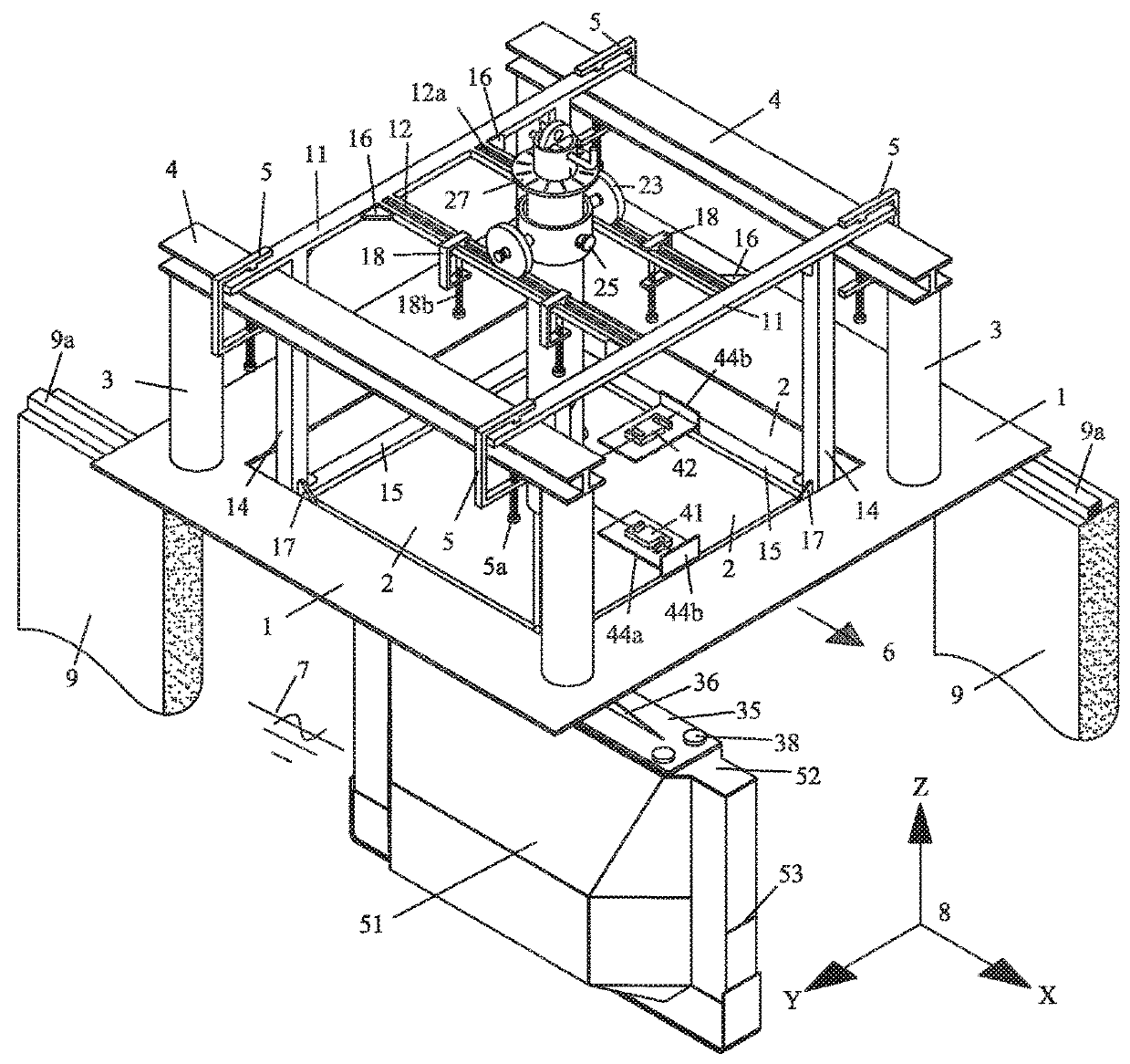
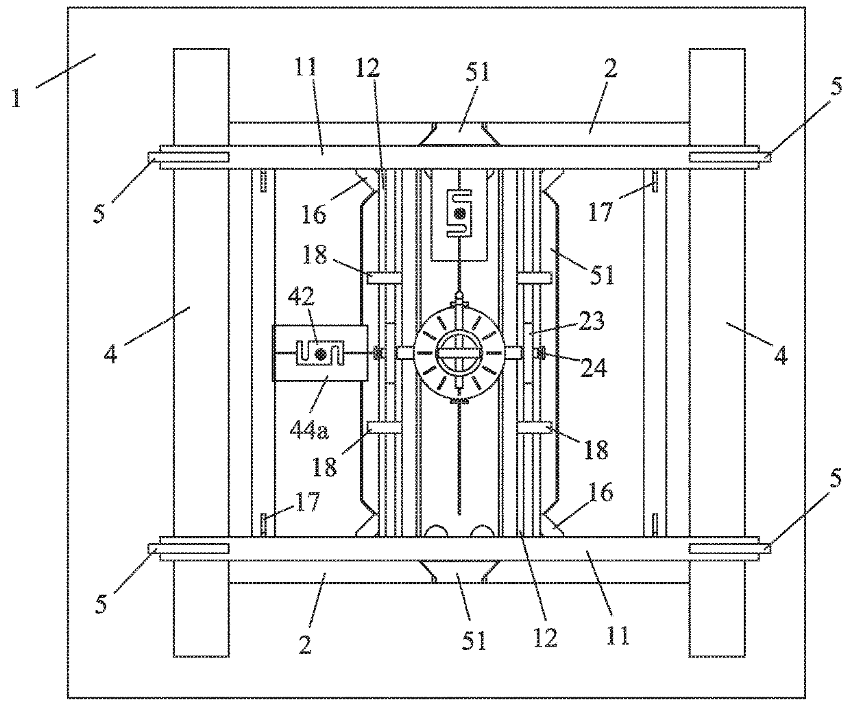
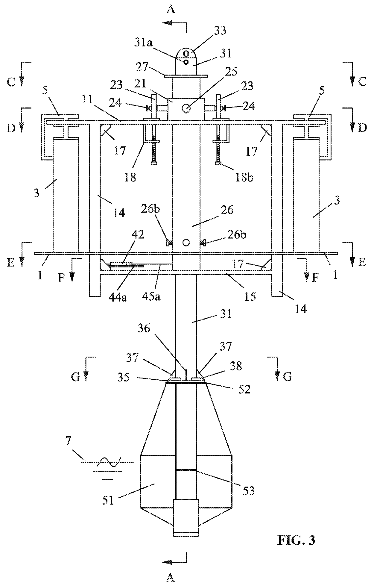
[0045]FIG. 1 shows a perspective view of a testing device for a model of a floating gate. FIGS. 2, 3, and 4 show respectively a top view, a front view, and a side view of the testing device for a model of a floating gate in FIG. 1. FIG. 5 shows a partial perspective view of the testing device for a model of a floating gate in FIG. 1. FIG. 7 shows a cross-sectional view taken from line B-B in FIG. 4. FIGS. 6, 8, 9, 10, 11, and 12 show respectively cross-sectional views taken along A-A, C-C, D-D, E-E, F-F, and G-G in FIG. 3. FIGS. 13, 14, and 15 show respectively enlarged views of parts K, L, and M in FIG. 5. FIG. 16 shows components of a data acquisition mechanism. FIG. 17 shows connections between various mechanisms of the testing device for a mod...


PUM


Abstract

A testing device for a model of a floating gate, the device including: a towing carriage including a platform and a moon pool; a square support mechanism including two upper transversal beams, two upper longitudinal beams, two I-shaped longitudinal beams, four lower beams, and straight plates disposed on two of the four lower beams; a dynamometric mechanism including a longitudinal tensiometer, a transversal tensiometer, and a signal transmitting terminal; a data acquisition mechanism including a computer and a signal receiving terminal; a casing mechanism including two stepped shafts and two rolling wheels; and a guide rod mechanism including an inner sleeve, an outer sleeve, and a connecting plate. One end of the connecting plate is connected to the lower end of the inner sleeve, and the other end thereof is connected to a deck of the floating gate.

Description

CROSS-REFERENCE TO RELATED APPLICATIONS[0001]Pursuant to 35 U.S.C. § 119 and the Paris Convention Treaty, this application claims foreign priority benefits to Chinese Patent Application No. 201710541407.9 filed Jul. 5, 2017, and to Chinese Patent Application No. 201720804595.5 filed Jul. 5, 2017. The contents of all of the aforementioned applications, including any intervening amendments thereto, are incorporated herein by reference.BACKGROUND OF THE INVENTIONField of the Invention[0002]The disclosure relates to a testing device for a model of a floating gate and a method of using the same.Description of the Related Art[0003]Typically, the speed test of ship models is performed in a towing tank. The water in the towing tank is stationary or in a wave-generating state. Conventionally, a towing carriage of a towing tank fails to produce flowing water with current of various angles, which means the hydrodynamic parameters of a model of a floating gate cannot be measured in a towing tan...

Claims


Application Information

Patent Timeline
Patent Type & Authority Patents(United States)
IPC IPC(8): F03B13/18B63B9/02G01M10/00B63B71/20
CPCB63B9/02F03B13/184G01M10/00B63B71/20Y02E10/30
Inventor LIN, YANJIANG, XIAONINGYU, YANYUNPEI, FEIGUAN, GUAN
Owner DALIAN UNIV OF TECH
Why Eureka
Try Eureka