Chassis structure

a technology of chassis and structure, applied in the direction of casings/cabinets/drawers, casings/cabinets/drawers, instruments, etc., can solve the problem of relatively high installation cost of sliding tracks, and achieve the effect of saving arrangement space and low installation cos

Active Publication Date: 2018-08-07
COMPAL ELECTRONICS INC
View PDF11 Cites 8 Cited by
  • Summary
  • Abstract
  • Description
  • Claims
  • Application Information

AI Technical Summary

Benefits of technology

[0004]The invention provides a chassis structure which requires relatively low installation costs and is able to save arrangement space.
[0017]Based on the above, in the chassis structure of the invention, the guiding assembly guides the frame to move upward and rotate relative to the chassis body by the first guiding slot and the second guiding slot thereof. As such, the end surface of the electronic module carried by the frame may be moved upward and rotate, and then the end surface is not blocked by the adjacent electronic module, so that a user may maintain the electronic module through the end surface conveniently. Accordingly, unlike conventional design, plural sliding tracks for adjacent electronic modules to be able to slide relatively and to be maintained conveniently are not required to be disposed, such that costs of installing the chassis structure may be reduced and arrangement space of the chassis structure may be saved.

Problems solved by technology

Nevertheless, costs of installing the sliding tracks are relatively high, and much allocation space in the server is also occupied by the sliding tracks.

Method used


Image

  • Chassis structure
  • Chassis structure
  • Chassis structure

Examples


Embodiment Construction

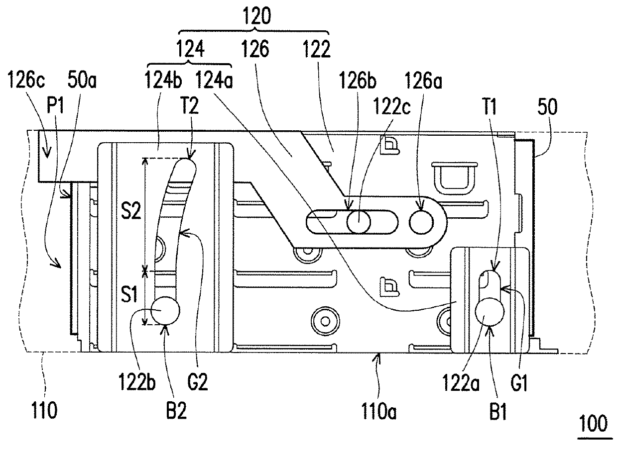
[0024]FIG. 1 is a partial side view of a chassis structure according to an embodiment of the invention. Referring to FIG. 1, a chassis structure 100 of the embodiment includes a chassis body 110 and at least one holder module 120 (one is illustrated). The holder module 120 includes a frame 122 and a guiding assembly 124. The frame 122 is located in the chassis body 110 and is configured to carry an electronic module 50. The frame 122 has a first linking portion 122a and a second linking portion 122b. The first linking portion 122a and the second linking portion 122b are configured to connect to the guiding assembly 124.

[0025]Specifically, the guiding assembly 124 is disposed in the chassis body 110 and has a first guiding slot G1 and a second guiding slot G2. The second guiding slot G2 has a first segment S1 and a second segment S2. The first guiding slot G1 and the first segment S1 extend along a straight direction (illustrated as a vertical direction), and the second segment S2 ex...


PUM

PropertyMeasurementUnit
rotation angleaaaaaaaaaa
heightaaaaaaaaaa
curvatureaaaaaaaaaa

Abstract

A chassis structure includes a chassis body and at least one holder module. The holder module includes a frame and a guiding assembly. The frame is located in the chassis body and has a first linking portion and a second linking portion. The guiding assembly is disposed on the chassis body and has a first guiding slot and a second guiding slot. The second guiding slot has a first segment and a second segment. The first guiding slot and the first segment extend along a straight direction, and the second segment extends along an arched direction. The first linking portion and the second linking portion are adapted to move along the first guiding slot and the first segment respectively at the same time such that the frame moves upward, and then the second linking portion is adapted to move along the second segment such that the frame rotates.

Description

CROSS-REFERENCE TO RELATED APPLICATION[0001]This application claims the priority benefit of U.S. provisional application Ser. No. 62 / 343,124, filed on May 30, 2016. The entirety of the above-mentioned patent application is hereby incorporated by reference herein and made a part of this specification.BACKGROUND OF THE INVENTION1. Field of the Invention[0002]The invention relates to a chassis structure. More particularly, the invention relates to a chassis structure in which an electronic module is able to be moved upward and rotate.2. Description of Related Art[0003]A server is a core computer used to serve computers or portable electronic devices in the network system. The server provides network users with functions such as disks required and printing services. Moreover, clients may share various resources in the network environment through the server. A plurality of hard disk modules are required to be disposed in the server in order to store large amount of data. As the hard disk...

Claims


Application Information

Patent Timeline
Patent Type & Authority Patents(United States)
IPC IPC(8): G06F1/18H05K5/02H05K7/14G11B33/12
CPCH05K7/1489G06F1/181G11B33/128H05K5/023H05K7/1415H05K7/1487H05K7/142H05K7/1457H05K7/1409G06F1/183G06F1/187A47B96/021
Inventor YU, WEI-CHENG
Owner COMPAL ELECTRONICS INC
Why Eureka
Try Eureka