Closing element for closing a container for samples for analysis

a technology for closing elements and samples, applied in the field of closing elements for samples, can solve the problems of unfavorable leakage through which bacteria could escape from the container, and achieve the effect of preventing cross-contamination between different sample analyses and effective displacement of gases

Active Publication Date: 2018-08-14
ENOSE HLDG
View PDF26 Cites 8 Cited by
  • Summary
  • Abstract
  • Description
  • Claims
  • Application Information

AI Technical Summary

Benefits of technology

[0006]The closing element is preferably configured such that the ventilating channel will open after a predefined external pressure has developed, optionally in combination at at least one predefined location on the closing element. Unintentional opening of the ventilating channel can in this way be prevented. It is also possible to envisage the closing element being configured such that the ventilating channel will open once a predefined internal gas pressure has developed, this generally being realized by the development of metabolic gas in the container. A high overpressure in the container can in this way be prevented, this generally being advantageous from a safety viewpoint. In this embodiment the closing element, and particularly the closing body, thus functions as a type of pressure relief valve.
[0023]The device preferably takes a mobile, in particular portable, form, whereby it is relatively easy to displace the device to a suitable location or destination. The mobile character of the device can considerably increase the applicability of the device. When the device comprises at least one electrical energy source which is at least coupled to the at least one chemical trace detector, the device can function fully autonomously, which is particularly advantageous. This can provide further advantage particularly in less developed countries because a mains supply is not usually available, or available to a limited extent.

Problems solved by technology

Creating a mutual distance between the at least one ventilating channel and the injection location can ensure that an injection needle pierces only the penetrable element during injection of a biological sample, and so not by mistake also the ventilating channel and the bacterial filter incorporated therein or co-acting therewith, which would result in undesired leakages via which bacteria could escape from the container.

Method used


Image

  • Closing element for closing a container for samples for analysis
  • Closing element for closing a container for samples for analysis
  • Closing element for closing a container for samples for analysis

Examples


Embodiment Construction

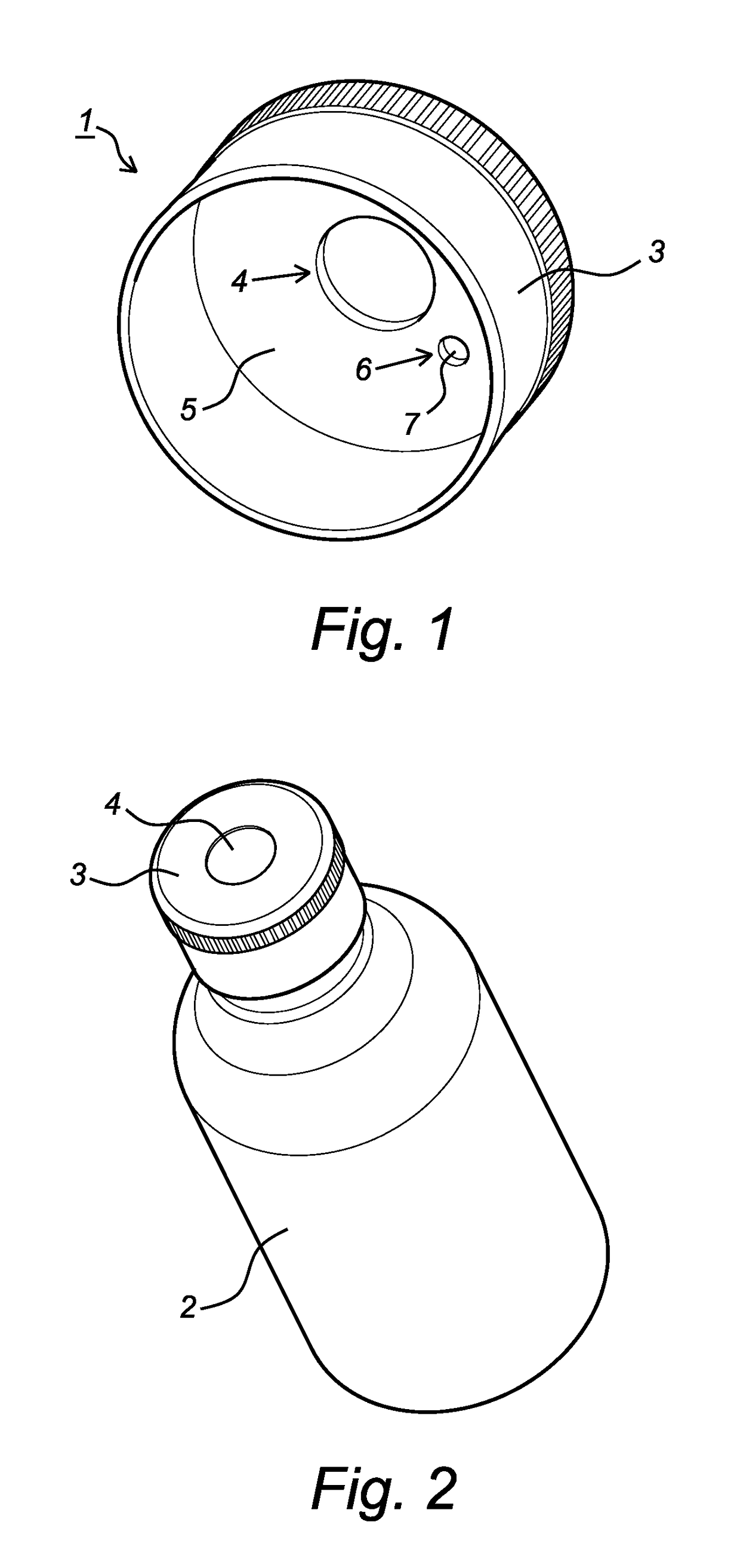
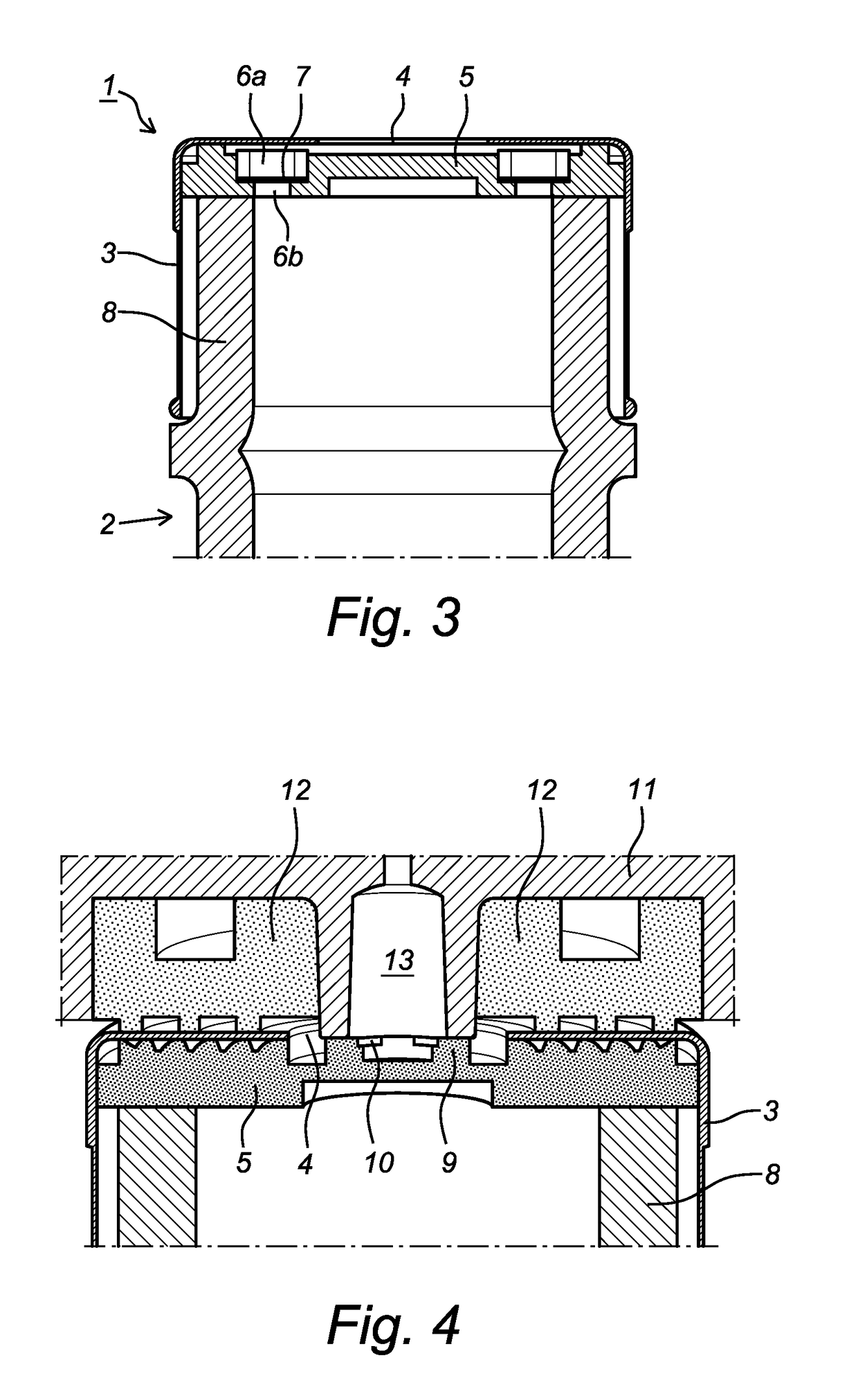
[0033]FIG. 1 is a perspective bottom view of a closing element 1 according to the invention. Closing element 1 is configured to be arranged on a container 2 for holding a biological (human or animal or vegetable) sample (see FIG. 2), wherein container 2 is partially enclosed by closing element 1. Closing element 1 here comprises a cap-like closing body 3 provided with a central (analysis) opening 4 which in practice will not be visible in the view according to FIG. 1 but is nevertheless drawn for the sake of completeness. Closing body 3 will generally be manufactured from plastic or metal. Central opening 4 is closed by a septum 5 which is manufactured from an elastomer and enclosed by closing body 3. Septum 5 is provided with a ventilating channel 6 provided with a membrane 7. Membrane 7 functions as bacterial filter, wherein bacteria cannot pass through membrane 7, while gas can pass through membrane 7 relatively unhindered. On a peripheral side the membrane 7 connects closely to ...


PUM

PropertyMeasurementUnit
diameteraaaaaaaaaa
diameteraaaaaaaaaa
diameteraaaaaaaaaa

Abstract

The application relates to a closing element for closing a container for samples for analysis, particularly biological samples. The application also relates to an assembly of a container and a closing element connected to the container. The application also relates to a device and method for analyzing samples. The closure comprises a vent channel (6) with a bacterial filter (7), a penetrable element (5) and the vent channel is configured to be connected with an analyzer and can be opened and closed.

Description

CROSS-REFERENCE TO RELATED APPLICATIONS[0001]This application is the United States national phase of International Application No. PCT / NL2013 / 050325 filed May 1, 2013, and claims priority to The Netherlands Patent Application No. 2008737 filed May 1, 2012, the disclosures of which are hereby incorporated in their entirety by reference.BACKGROUND OF THE INVENTIONField of the Invention[0002]The invention relates to a closing element for closing a container for samples, particularly biological samples. The invention also relates to an assembly of a container and a closing element connected to the container. The invention also relates to a device for analysing samples, particularly biological samples, by making use of an assembly according to the invention. In addition, the invention relates to a method for analysing samples, particularly biological samples, by making use of an assembly according to the invention.Description of Related Art[0003]The use of electronic noses makes it possi...

Claims


Application Information

Patent Timeline
Patent Type & Authority Patents(United States)
IPC IPC(8): B01L3/00G01N33/497C12Q1/02G01N1/22
CPCB01L3/50825C12Q1/02G01N33/497B01L2200/026G01N2033/4977B01L2300/044B01L2300/048G01N2001/2229B01L2200/0684
Inventor BOS, ALBERT
Owner ENOSE HLDG
Why Eureka
Try Eureka