Supercharge Your Innovation With Domain-Expert AI Agents!

Attaching and detaching device and robot

a technology of attachment and detachment device, which is applied in the direction of manipulators, gripping heads, multi-purpose tools, etc., can solve the problems of increasing the cost of building the robot system, complex structure of the robot system, and difficulty in or inability to detach, so as to facilitate the attachment and detachment of two structures and simple operation

Active Publication Date: 2018-08-14
SEIKO EPSON CORP
View PDF63 Cites 2 Cited by
  • Summary
  • Abstract
  • Description
  • Claims
  • Application Information

AI Technical Summary

Benefits of technology

The invention provides a device and robot that can easily attach and detach two structures with simple operations. This simplifies the process of connecting and disconnecting the structures, which improves efficiency and flexibility in various applications.

Problems solved by technology

Therefore, since the robot system includes the detaching tool, the structure (the configuration) of the robot system is complicated.
If the detaching tool is lost, the detaching work is difficult or impossible.
Further, costs for building the robot system increase.

Method used


Image

  • Attaching and detaching device and robot
  • Attaching and detaching device and robot
  • Attaching and detaching device and robot

Examples


first embodiment

[0070]An attaching and detaching device and a robot according to this embodiment are explained in detail below on the basis of preferred embodiments shown in the accompanying drawings.

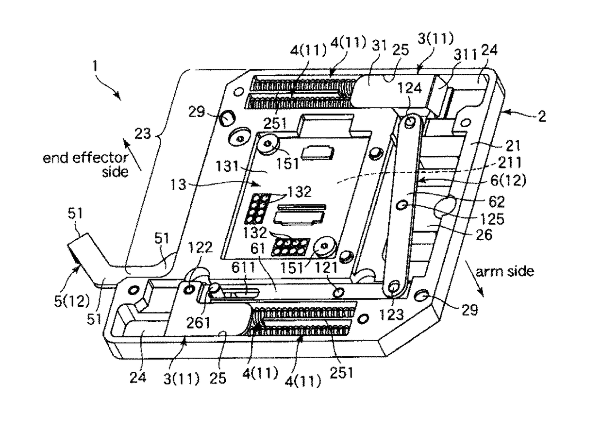
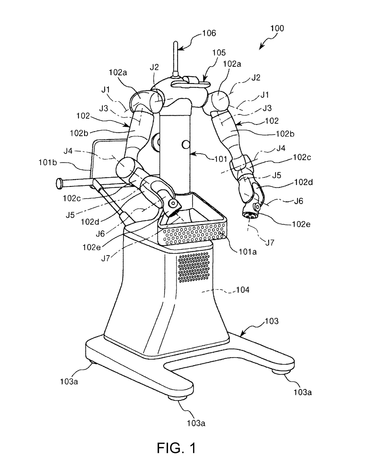
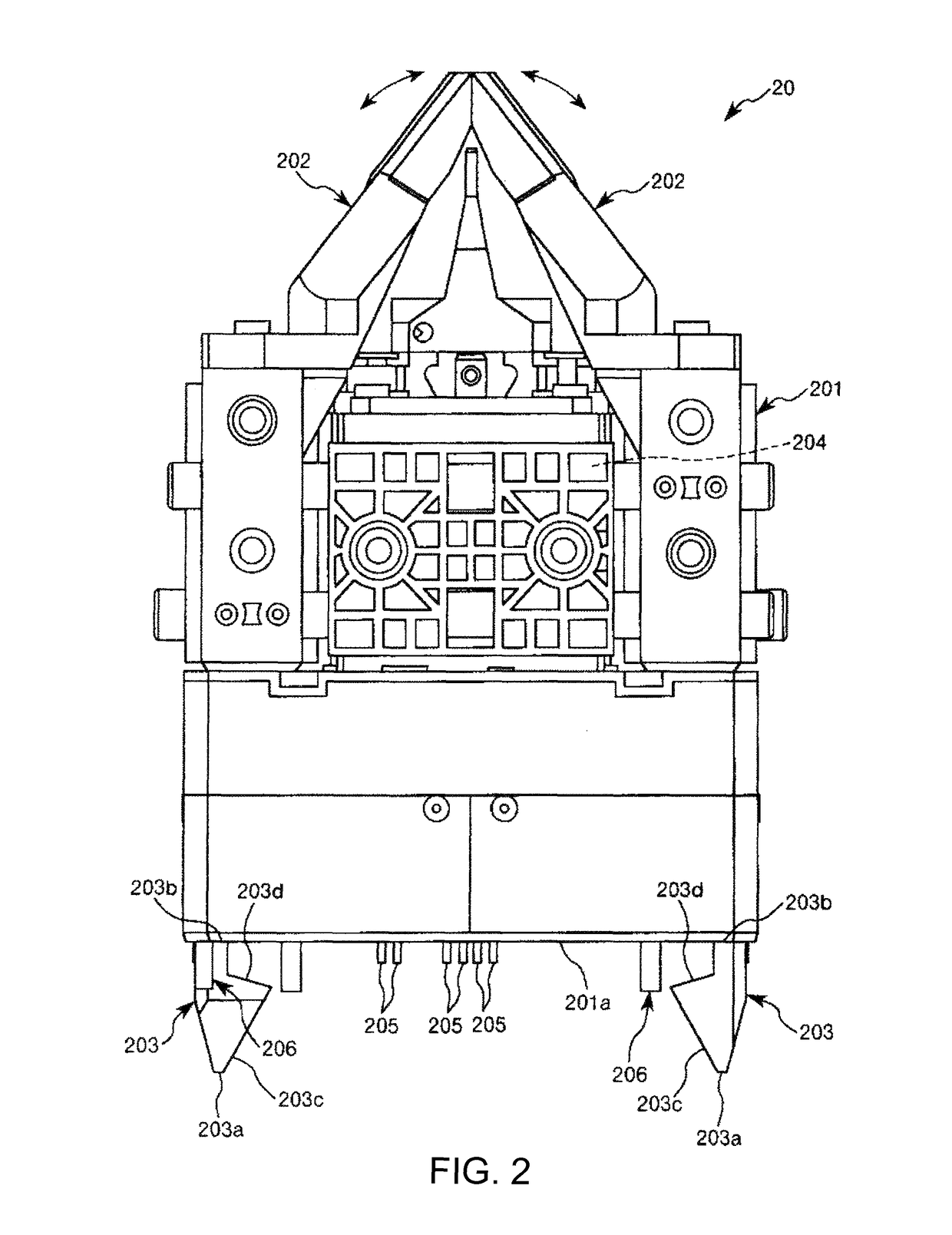
[0071]FIG. 1 is a perspective view showing an embodiment in which a robot according to this embodiment is applied to a humanoid double-arm robot. FIG. 2 is a side view of an end effector attached to an arm of the robot shown in FIG. 1. FIG. 3 is a perspective view of the end effector shown in FIG. 2. FIG. 4 is a perspective view showing an attaching and detaching device according to this embodiment. FIGS. 5 and 6 are respectively perspective views showing operation states of detachment and attachment of an internal structure on the front side of the attaching and detaching device shown in FIG. 4. FIGS. 7 and 8 are respectively perspective views showing operation states of detachment and attachment of an internal structure on the rear side of the attaching and detaching device shown in FIG. 4. FIG. 9 is...

second embodiment

[0136]FIG. 12 is a perspective view showing an attaching and detaching device according to this embodiment. FIGS. 13 and 14 are respectively perspective views showing an attached state and detached state of an internal structure on the front side of the attaching and detaching device shown in FIG. 12. FIGS. 15 to 17 are respectively perspective views showing a prohibiting state, a permitting state, and a detached state of a lever for lock of an internal structure on the rear side of the attaching and detaching device shown in FIG. 12. FIG. 18 is a sectional view taken along line A-A in FIG. 15. FIG. 19 is a sectional view taken along line B-B in FIG. 15. FIG. 20 is a sectional view taken along line C-C in FIG. 16. FIG. 21 is a partial longitudinal sectional view showing a state in which an end effector is attached to the attaching and detaching device according to this embodiment. FIG. 22 is a partial longitudinal sectional view of the attaching and detaching device changed from the...


PUM


Abstract

An attaching and detaching device that detachably attaches two structures includes a base fixed to one structure of the two structures and formed in a tabular shape, one or more engaging members supported by the base movably along a surface direction of the base and configured to engage with the other structure, an urging member configured to urge the engaging member toward an engaging direction in which the engaging member engages with the other structure, and a releasing mechanism including an operation lever configured to perform operation for moving the engaging member in a direction opposite to the engaging direction and releasing an attached state in which the two structures are attached to each other.

Description

BACKGROUND[0001]1. Technical Field[0002]The present invention relates to an attaching and detaching device and a robot.[0003]2. Related Art[0004]There has been known a robot arm including a base and a plurality of arms supported displaceably with respect to the base and coupled to one another. An end effector (a robot hand) is detachably attached to a distal end of the robot arm. The robot arm is used in an attached state of the end effector (see, for example, JP-A-7-290389 (Patent Literature 1)).[0005]When the end effector described in Patent Literature 1 is detached from the robot arm and replaced with another end effector, work for detaching the end effector is performed using an exclusive detaching tool (a stock pin) provided separately from the end effector. Therefore, since the robot system includes the detaching tool, the structure (the configuration) of the robot system is complicated. If the detaching tool is lost, the detaching work is difficult or impossible. Further, cos...

Claims


Application Information

Patent Timeline
Patent Type & Authority Patents(United States)
IPC IPC(8): B25G3/18B25J15/04
CPCB25J15/0408Y10T403/60Y10S483/901
Inventor GOTO, YOSHINOBUTANAKA, TOSHIO
Owner SEIKO EPSON CORP
Features
  • R&D
  • Intellectual Property
  • Life Sciences
  • Materials
  • Tech Scout
  • Unparalleled Data Quality
  • Higher Quality Content
  • 60% Fewer Hallucinations
Learn More