Ventilating fan

a ventilating fan and fan body technology, applied in ventilation systems, lighting and heating apparatus, heating types, etc., can solve the problems of uneven reduction of air outlet, difficult to smoothly transform the air blown by the sirocco fan b>120/b>, and generating turbulence, so as to ensure the wind amount of the ventilating fan, reduce noise, and ensure the effect of high efficiency

Active Publication Date: 2018-08-14
PANASONIC ECOLOGY SYSTEMS GUANGDONG CO LTD +1
View PDF47 Cites 9 Cited by
  • Summary
  • Abstract
  • Description
  • Claims
  • Application Information

AI Technical Summary

Benefits of technology

[0015]Accordingly, an object of the present invention is to provide a ventilating fan that can provide a greater wind amount with a sirocco fan having the same performance as described above.
[0016]Another object of the present invention is to provide a ventilating fan that can achieve a quieter operation with a sirocco fan having the same performance as described above.
[0031]The present invention is advantageous in that no turbulence is generated at the adapter and the wind amount of the ventilating fan is thus ensured and noise is reduced. Therefore, the present invention can provide a small air blowing device with high efficiency and improve stability of performance of the product.

Problems solved by technology

The above air blowing device of the prior art has the following problems: the air blown by the sirocco fan 120 is difficult to be smoothly transformed since the square shape of the air outlet 112 is different from the round shape of the duct.
That is to say, the air blown by the sirocco fan 120 is not uniform and thus prone to generate turbulence although the air outlet is evenly reduced.
The ventilating fan cannot ensure amount of the blown air due to this turbulence.
However, the large sirocco fan will generate stronger noise.
The adapter structure cannot be smoothly connected with the casing provided with the fan since the area of the air inlet 1110 is too large.

Method used


Image

  • Ventilating fan
  • Ventilating fan
  • Ventilating fan

Examples


Embodiment Construction

[0043]Exemplary embodiments of the present disclosure will be described hereinafter in detail with reference to the attached drawings, wherein the like reference numerals refer to the like elements. The present disclosure may, however, be embodied in many different forms and should not be construed as being limited to the embodiment set forth herein; rather, these embodiments are provided so that the present disclosure will be thorough and complete, and will fully convey the concept of the disclosure to those skilled in the art.

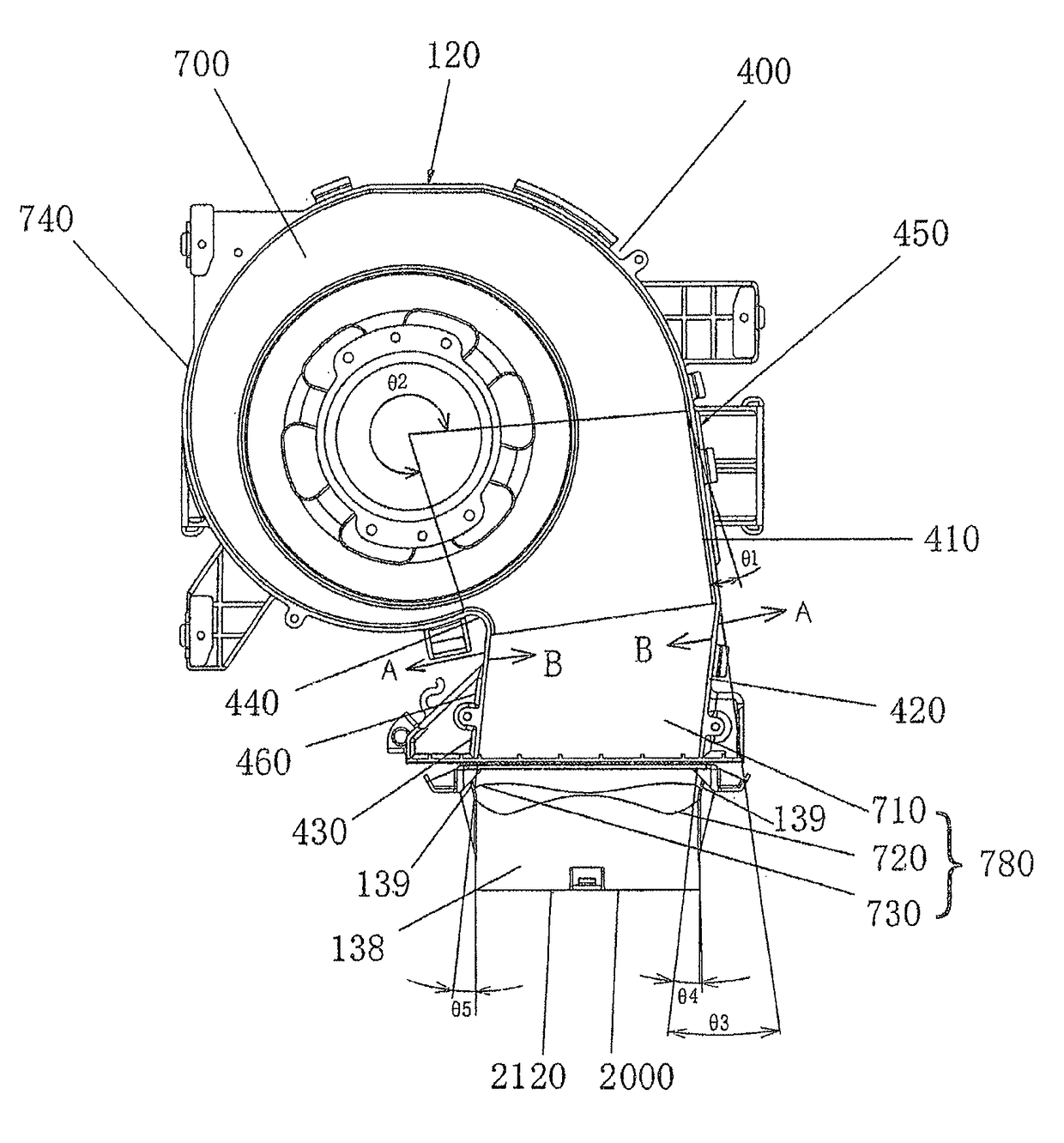
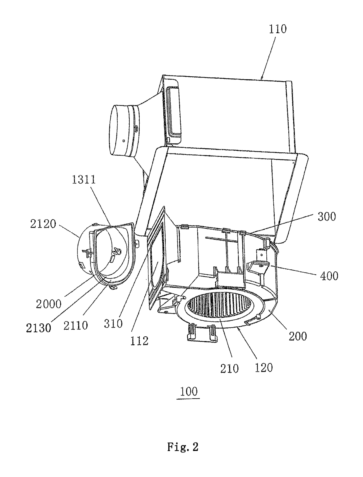
[0044]FIGS. 2 and 3 show schematic views of an embodiment of the present invention. A ventilating fan 100 comprises a sirocco fan 120 disposed in a box-shaped body 110 and an adapter 2000 connected with a square air outlet 112 of the sirocco fan 120. The sirocco fan 120 is composed of a first scroll plate 200 and a second scroll plate 300, which have opposite complementary shapes, and a casing plate 400 sandwiched between the two scroll plates. An overall air...


PUM


Abstract

A ventilating fan includes a sirocco fan disposed in a box-shaped body and an adapter connected to an air outlet of the sirocco fan. The sirocco fan is composed of two opposite scroll plates with scroll shapes and a casing plate sandwiched between the two scroll plates. An overall air inlet of the sirocco fan is disposed on the first scroll plate and a central line of the air outlet of the adapter is offset towards the second scroll plate. The present invention is advantageous in that no turbulence is generated at the adapter and the wind amount of the ventilating fan is thus ensured and noise is reduced. Therefore, the present invention can provide a small air blowing device with high efficiency and improve stability of performance of the product.

Description

CROSS-REFERENCE TO RELATED APPLICATION[0001]This application claims the benefit of Chinese Patent Application No. 201010130174.1 filed on Mar. 17, 2010, and Chinese Patent Application No. 201010130195.3 filed on Mar. 17, 2010 in the State Intellectual Property Office of China, the disclosure of which is incorporated herein by reference.BACKGROUND OF THE INVENTION[0002]1. Field of the Invention[0003]The present invention relates to a structure of an air blowing device, and particularly to a ventilating fan in which a sirocco fan is provided.[0004]2. Description of the Related Art[0005]A known ventilating fan 100 is shown in FIG. 1. A sirocco fan 120 is disposed in a box-shaped body 110. An air is suctioned through an air inlet 111 at a bottom of the body 110 and discharged to the outdoors through an air outlet 112 on a side of the body 110. Furthermore, a metal adapter 1500 is disposed at the air outlet 112 on the side of the body 110 so as to discharge the air to the outdoors throug...

Claims


Application Information

Patent Timeline
Patent Type & Authority Patents(United States)
IPC IPC(8): F24F7/013F04D29/42F04D29/62F04D29/44F04D25/08F04D5/00F04D29/66
CPCF04D25/08F04D29/422F04D29/4213F04D29/441F04D29/626F04D29/663F04D29/4226F05D2250/51
Inventor YANG, ZHENJIANGAO, SHOUYONGYANG, JINGTAOLONG, MINRAO, ZEWEIZHU, JIANRONG
Owner PANASONIC ECOLOGY SYSTEMS GUANGDONG CO LTD
Why Eureka
Try Eureka