Handheld blower

a handheld blower and blower technology, applied in the field of electric garden tools, can solve the problems of long working time of the described handheld blower and large air flow rate, and achieve the effects of reducing air resistance, enhancing blowing efficiency, and improving airflow characteristics

Active Publication Date: 2014-08-21
CHERVON HK LTD WANCHAI
View PDF43 Cites 21 Cited by
  • Summary
  • Abstract
  • Description
  • Claims
  • Application Information

AI Technical Summary

Benefits of technology

[0014]The handheld blower defines a central axis on the blowpipe, and along the direction of the central axis, the area of the flowing cross-section of the air passage at the rear end of the fan adjacent to the air inlet is larger than that at the air outlet of the blowpipe. Such arrangement can effectively improve the flow characteristic of the airflow and enhance the blowing efficiency. Additionally, the rate between the area of the flow cross-section of the air outlet of the blowpipe and the area of the flow cross-section of the flow-through area at the position of the fan is larger than or equal to 0.8, which effectively reduces the air resistance caused by the airflow and the airflow loss on the wall of the air passage as well as the loss of the high-speed airflow in the blowpipe, thus the blowing efficiency of the whole machine may be increased.
[0015]The battery of the handheld blower has a capacity larger than 170 wh, which can provide sufficient power to the blower, thus it can increase the working time, enhance the air flow rate, and reduce the times of changing the battery pack, and the operation is more convenient.
[0016]The handheld blower uses an axial fan having an outer diameter in the range from 85 mm to 140 mm. Such arrangement enables the blower to have a large air flow rate sufficient to blow plenty of fallen leaves on the ground or some relatively heavy garbage thereby meeting the requirements of the operator.

Problems solved by technology

The described handheld blower will also have a long working time and a large air flow rate.

Method used


Image

  • Handheld blower
  • Handheld blower
  • Handheld blower

Examples


Embodiment Construction

[0026]In order to better understand the technical content of the present invention, the following will describe preferred embodiments with reference to the drawings in detail.

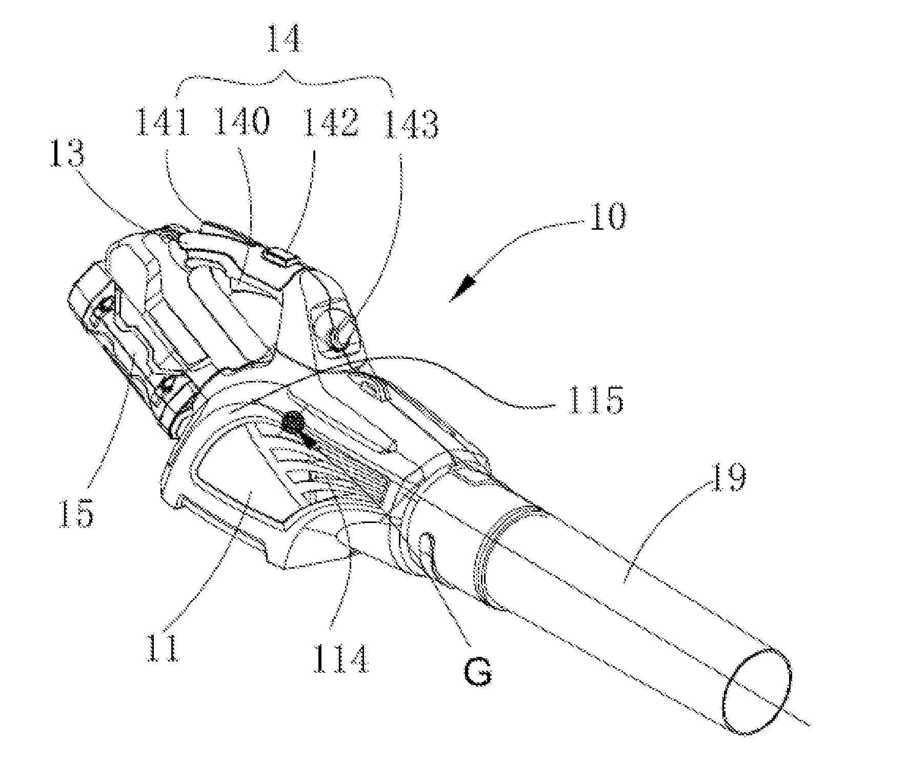
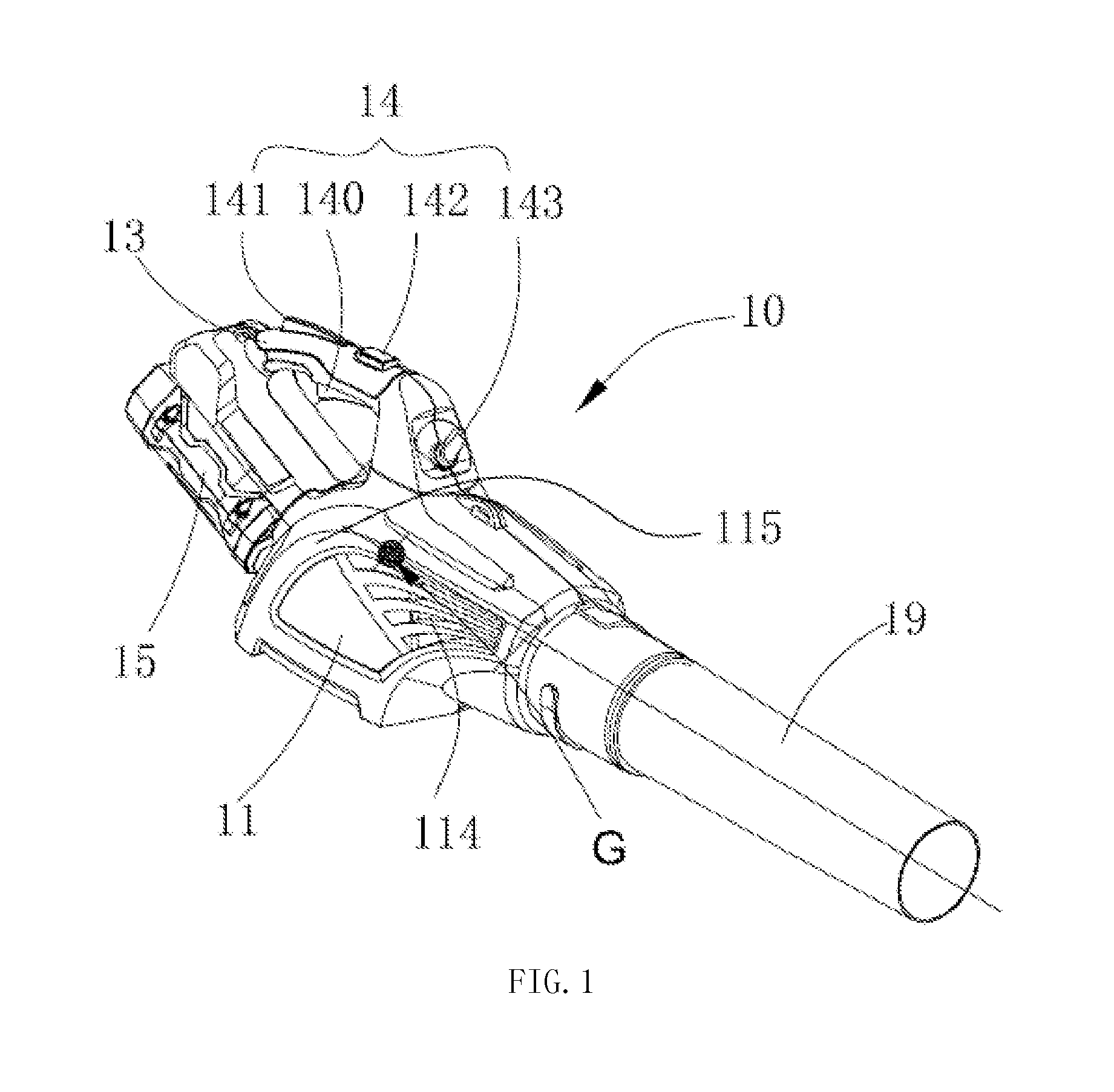
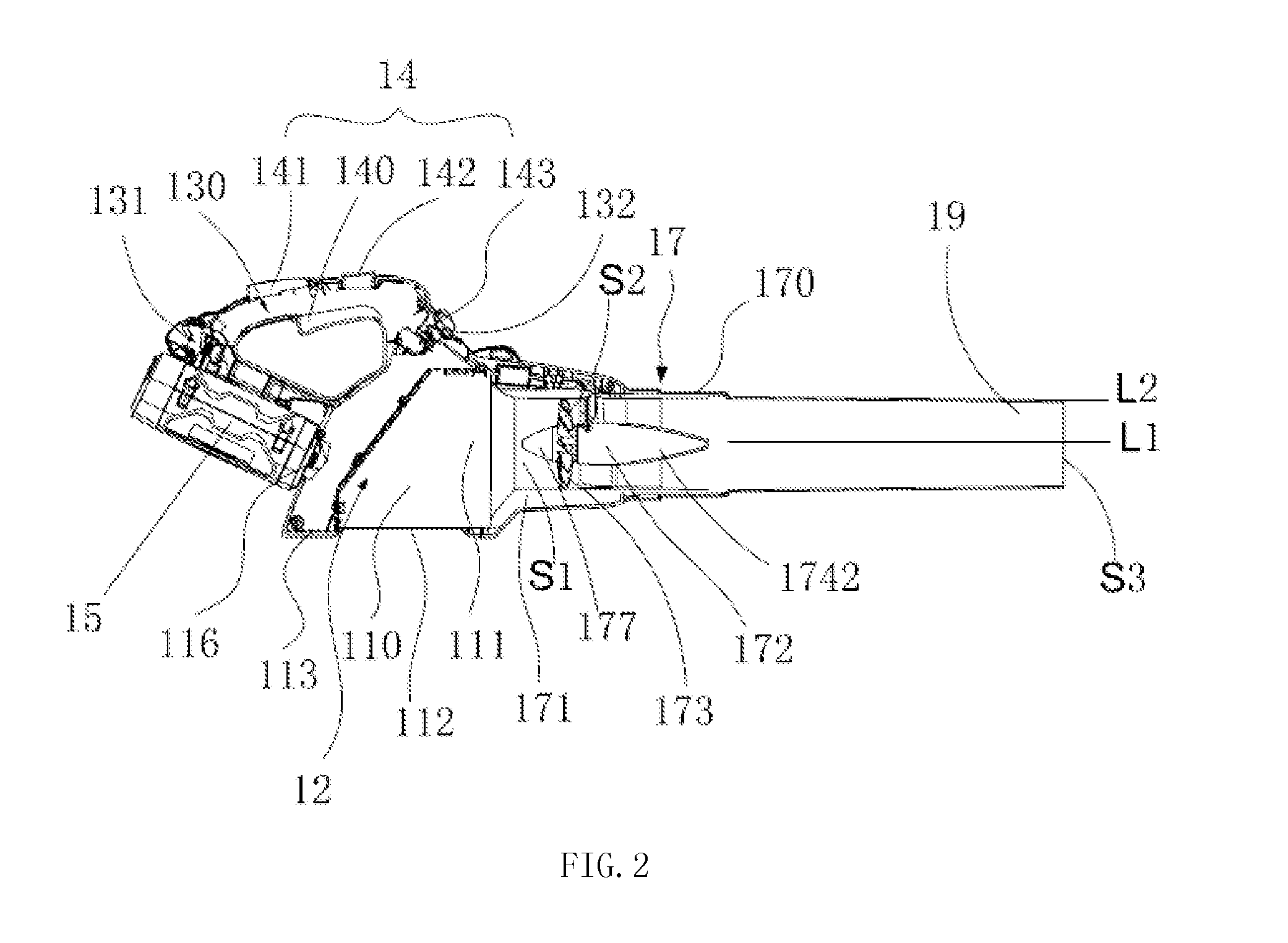
[0027]Referring to FIG. 1 and FIG. 2, in one embodiment of the present invention, the handheld blower 10 includes a housing 11, an air intake box 12, a handle 13, a control assembly 14, a battery 15, a duct assembly 17 and a blowpipe 19. The battery 15 and the duct assembly 17 are arranged on opposite ends of the housing 11 and the handle 13 is arranged on the housing 11. The housing 11 is connected with the blowpipe 19 by the duct assembly 17, and the air intake box 12 is arranged in the housing 11.

[0028]Referring to FIGS. 2 and 3, the housing 11 includes an accommodating chamber 110, a mounting portion 111, a main air inlet 112, a secondary air inlet 113, a side air inlet 114 and a bending portion 115. The accommodating chamber 110 is formed in the housing 11, the air intake box 12 is mounted in the accommoda...


PUM


Abstract

A handheld blower includes a housing, the housing including an air inlet and a duct assembly, the duct assembly including a duct, a motor and a fan mounted in the duct, a battery, a handle, and a blowpipe which defines a central axis. Along the direction of the central axis, the area of the flowing cross-section of an air passage at the rear end of the fan adjacent to the air inlet is larger than that of the flowing cross-section of an air outlet of the blowpipe, and the rate between the area of the flow cross-section of the air outlet of the blowpipe and the area of the flow cross-section of the flow-through area at the position of the fan is greater than or equal to 0.8.

Description

RELATED APPLICATION INFORMATION[0001]This application claims the benefit of CN 201310054133.2, filed on Feb. 20, 2013, CN 201310108035.2, filed on Mar. 29, 2013, CN 201310109907.7, filed on Mar. 29, 2013, and CN 201310109908.1, filed on Mar. 29, 2013 the disclosures of which are incorporated herein by reference in their entirety.FIELD OF THE PRESENT DISCLOSURE[0002]The present disclosure relates to electrical garden tools and, more particularly, to a handheld blower.BACKGROUND[0003]A garden handheld blower is mainly powered in two manners, i.e., by use of an external power supply or a battery pack. If an external power supply is used, the machine can only be used in applications with a power interface which greatly limits the application scope of the handheld blower. While using a battery pack can solve this problem, in the case of the battery pack the weight and the size of the battery pack is generally large in order to ensure sufficient usage capacity. As the capacity of the batt...

Claims


Application Information

Patent Timeline
Patent Type & Authority Applications(United States)
IPC IPC(8): E01H1/08
CPCE01H1/0809A01G20/47A47L5/14A47L9/22
Inventor YAMAOKA, TOSHINARIGUO, JIANPENGNIE, FANGJIESHAO, XIANDIAN
Owner CHERVON HK LTD WANCHAI
Why Eureka
Try Eureka