Heating and ventilating air-conditioning system and control method thereof

A HVAC system and control unit technology, applied in air handling equipment, heating/cooling equipment, transportation and packaging, etc., can solve the problems of lowering, increasing noise, increasing energy consumption, etc., to improve comfort and reduce Effects of local pressure loss and air volume increase

Inactive Publication Date: 2008-09-10
CHERY AUTOMOBILE CO LTD
View PDF0 Cites 20 Cited by
  • Summary
  • Abstract
  • Description
  • Claims
  • Application Information

AI Technical Summary

Problems solved by technology

Therefore, the above-mentioned structure causes the air volume to decrease due to the resistance of the evaporator core in ventilation and heating modes, and also increases noise and energy consumption

Method used


Image

  • Heating and ventilating air-conditioning system and control method thereof
  • Heating and ventilating air-conditioning system and control method thereof
  • Heating and ventilating air-conditioning system and control method thereof

Examples


Embodiment 1

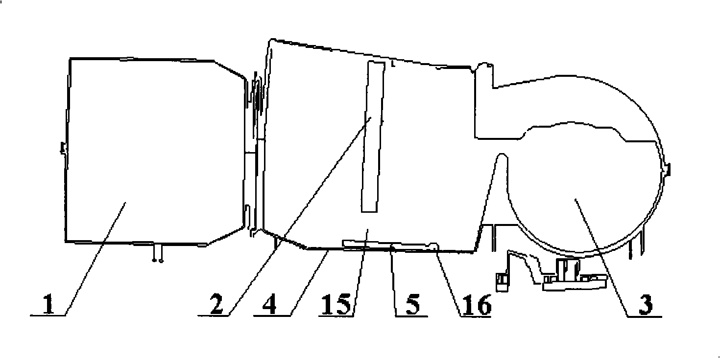
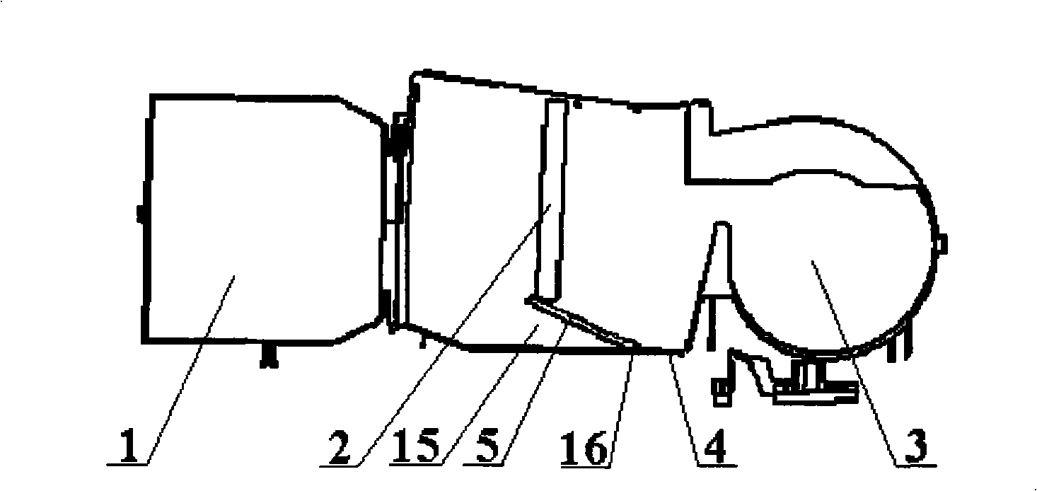
[0045] On the basis of the above technical solution, the evaporator bypass air door 5 is provided with a bypass air door rotating shaft 16 connected as a whole, and the bypass air door rotating shaft 16 is installed on the evaporator shell 4, so that The evaporator bypass air door 5 can rotate with the axis of the rotating shaft as the center of rotation.

[0046] The bypass air door rotating shaft 16 constitutes the rotation center of the evaporator bypass air door 5 and can be installed on the evaporator housing 4 .

Embodiment 2

[0048] The bypass air door rotating shaft 16 is set at the position of the evaporator shell 4 and staggers a certain distance from the evaporator core 2 and is biased towards the direction of the blower 3; the axis of the bypass air door rotating shaft 16 is perpendicular to the gas flow in the evaporator shell. The direction in which the body 4 flows; the evaporator bypass air door 5 forms an oblique angle with the cross section of the evaporator shell 4 when it is closed, and after the evaporator bypass air door 5 is completely closed, its edge and the evaporator core 2 close.

[0049] The purpose of the above structure setting is to make the evaporator side air door 5 completely closed, and under the action of the air flow, it can be tightly attached to the evaporator core 2, forcing the air flow to pass through the evaporator core 2 to better reduce the air flow. temperature. And after the evaporator bypass air door 5 is fully opened, the resistance to air flow is reduced...

Embodiment 3

[0052] The bypass air door rotating shaft 16 extends out of the evaporator housing 4, and a bypass air door driving motor is arranged outside the evaporator housing 4, and is connected with the bypass air door rotating shaft 16 through a mechanical transmission mechanism.

[0053] The mechanical transmission mechanism mentioned above may be a gear transmission mechanism, or a worm gear transmission mechanism, or other mechanical transmission mechanisms. The mechanical transmission mechanism is used for deceleration, and when the shaft of the drive motor of the bypass door rotates, the opening and closing of the bypass door 5 of the evaporator is driven.


PUM


Abstract

The invention discloses a heating ventilating air conditioning system. A blower (3), the core body of an evaporator (2) and a distribution case (1) are arranged on the air current channel of the heating ventilating air conditioning system and the core body of the evaporator (2) is arranged in an evaporator shell (4); a bypass gap (15) is arranged between the side surface of the core body of the evaporator (2) and the evaporator shell (4) and an evaporator bypass damper (5) which can be opened and closed is arranged on the bypass gap. When the evaporator bypass damper (5) is closed, the evaporator bypass damper can fully close the bypass gap (15). By adopting the technical scheme, the airflow passes through the bypass damper basically instead of the core body of the evaporator when the heating ventilating air conditioning system is in a ventilating mode or a heating mode, thus reducing the pressure loss of the airflow, increasing the air volume, reducing the noise and enhancing the inside driving comfort in case of the same blower power.

Description

technical field [0001] The invention belongs to the technical field of automobile structure, and relates to an HVAC system used in automobiles. In addition, the present invention also relates to a control method adopted by the above-mentioned HVAC system. Background technique [0002] As the user's requirements for the comfort of the car's interior environment are increasing day by day, providing a comfortable and clean air environment in the car has become an important research topic for car product design. Among the above-mentioned subjects, as a device for providing comfortable air in the car, the car air-conditioning system is in the most important and critical position. At present, the automotive air conditioning system provides comfortable air for the interior of the vehicle through the HVAC system assembly. The functions and functions of the HVAC system assembly are: [0003] 1. Perform air purification treatment on the circulating air, that is, filter and replace ...

Claims


Application Information

Patent Timeline
Patent Type & Authority Applications(China)
IPC IPC(8): B60H1/00
Inventor 刘慧军刘志勇周定华代建红
Owner CHERY AUTOMOBILE CO LTD
Why Eureka
Try Eureka