A Composite Pneumatic Conveying Swirl Elbow

A pneumatic conveying pipeline and swirl technology, applied in the field of coal particle pneumatic conveying pipeline, can solve the problems of intensified particle collision and crushing, coal dust polluting the environment, and low energy efficiency of conveying, so as to reduce local pressure loss, improve material conveying quality, small size effect

Active Publication Date: 2020-08-11
CHINA UNIV OF MINING & TECH
View PDF7 Cites 0 Cited by
  • Summary
  • Abstract
  • Description
  • Claims
  • Application Information

AI Technical Summary

Problems solved by technology

[0003] However, in the current process of coal pneumatic transportation, pipeline wear is still unavoidable, resulting in low energy efficiency in transportation, and a large amount of coal dust overflows and pollutes the environment, especially in elbow pipes.
In addition, the pressure loss in the pneumatic conveying system includes pressure loss along the way and local pressure loss. It is mainly manifested as local pressure loss at the bend. The velocity and flow direction of the particle flow change sharply with the bend, resulting in a velocity gradient and resulting in a flow field Turbulent flow is formed inside, which intensifies the collision and fragmentation between particles

Method used


Image

  • A Composite Pneumatic Conveying Swirl Elbow

Examples


Embodiment Construction

[0010] In order to make the purpose, technical solutions and advantages of the embodiments of the present invention clearer, the technical solutions in the embodiments of the present invention will be clearly and completely described below in conjunction with the drawings in the embodiments of the present invention. Obviously, the described embodiments It is a part of embodiments of the present invention, but not all embodiments. Based on the embodiments of the present invention, all other embodiments obtained by persons of ordinary skill in the art without making creative efforts belong to the protection scope of the present invention.

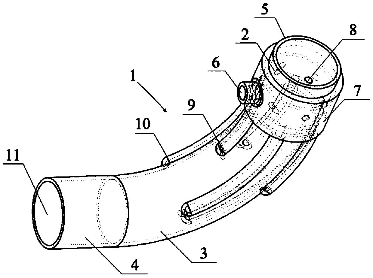
[0011] figure 1 A schematic diagram of the structure of a preferred embodiment of the present invention is shown. A composite pneumatic conveying swirl elbow in the figure includes a pipe body 1 for conveying fluid, and the pipe body 1 includes an inlet straight pipe portion, There are three parts: the bend pipe part and the outlet straight ...


PUM


Abstract

Provided is a composite pneumatic transport rotational flow elbow pipe. The composite pneumatic transport rotational flow elbow pipe includes a pipe body for transporting fluid; the pipe body includesan inlet straight pipe part, an elbow pipe part and an outlet straight pipe part. The inlet straight pipe part includes an inlet straight pipe segment, a gas-solid mixture inlet, a rotational flow gas inlet, a rotational flow gas mixing chamber and a rotational flow generation hole; the elbow pipe part includes an elbow pipe segment, a primary rotational flow generation pipe and a secondary rotational flow generation pipe; the outlet straight pipe part includes an outlet straight pipe segment and a gas-solid mixture outlet which is formed in the end portion of the outlet straight pipe segment. By adopting the composite pneumatic transport rotational flow elbow pipe, adequate rotational flow gas can be generated, rotational flow transportation is achieved, collision and friction between particles and a pipe wall are effectively reduced, the material transport quality is improved, the service life of the composite pneumatic transport rotational flow elbow pipe is effectively prolonged,meanwhile, local pressure loss is reduced, and the working efficiency of a pneumatic transport system is improved.

Description

technical field [0001] The invention relates to a coal particle pneumatic conveying pipeline, in particular to a composite pneumatic conveying swirl elbow. Background technique [0002] Coal is the basic energy and important raw material of our country, and the coal industry is related to the lifeline of the national economy. With the rapid development of the national economy, my country's demand for coal is increasing day by day. The coal transportation link occupies a large proportion of the cost of coal mining. The existing underground transportation equipment and supporting facilities are complicated, and safety accidents occur frequently. Pneumatic conveying is a transportation technology that uses airflow at a certain pressure and speed to convey granular materials. It has been widely used in petroleum, chemical and food processing and other fields. It is clean, green and has a high recycling rate. [0003] However, in the current process of coal pneumatic transporta...

Claims


Application Information

Patent Timeline
Patent Type & Authority Patents(China)
IPC IPC(8): B65G53/52
CPCB65G53/521B65G53/523
Inventor 李建平周锋杨道龙田世伟田超李雨泽罗江南周后宇
Owner CHINA UNIV OF MINING & TECH
Why Eureka
Try Eureka