System and method for condensate blockage removal with ceramic material and microwaves

a technology of ceramic material and condensate, which is applied in the field of operations in the wellbore, can solve the problems of near-wellbore formation damage (or blockage), accumulated liquids can impede the gas flow path from the reservoir towards the wellbore, and the well has to be abandoned, so as to prevent or reduce the accumulation of condensates, and improve the gas recovery

Active Publication Date: 2018-08-21
SAUDI ARABIAN OIL CO
View PDF62 Cites 11 Cited by
  • Summary
  • Abstract
  • Description
  • Claims
  • Application Information

AI Technical Summary

Benefits of technology

[0008]There is a need for efficient and economical systems and methods for removal of condensed fluids from the wellbore and near-wellbore regions. Described are systems and methods for reducing or removing condensate blockage in and around a wellbore producing hydrocarbons, for example natural gas. Microwaves are used to heat a ceramic-containing material within a near-wellbore formation. Heat is transferred from the ceramic-containing material to the near-wellbore formation. Any gas condensate, or other condensed fluid, reservoirs in the near-wellbore formation are heated, and condensed liquids accumulated around the wellbore are re-evaporated. In formations with little or no gas condensate reservoirs, maintaining near-wellbore formation temperature greater than the dew-point line of fluids can improve gas recovery from reservoirs by preventing or reducing accumulation of condensates.
[0009]Maintenance of the production fluid in the vapor phase avoids condensation associated with liquid loading and reduces the corrosive effects of the production fluid on the production tubing. The systems and methods described can be used to rapidly heat a near-wellbore formation to a desired temperature in a timely, efficient, and low-cost way in order to remove condensed fluid from near-wellbore formations in wells used in hydrocarbon recovery.
[0015]Also disclosed is a method of reducing the presence of condensed fluid in a wellbore and a near-wellbore formation. The method includes the steps of disposing a ceramic-containing material within the wellbore and proximate to a reservoir formation, where the reservoir formation comprises hydrocarbon-bearing strata and providing a microwave producing unit operable to heat the ceramic-containing material, where the microwave producing unit comprises a microwave antenna disposed within the wellbore and proximate the ceramic-containing material. The method further includes the steps of activating the microwave producing unit to heat the ceramic-containing material, where the ceramic-containing material is operable to absorb microwaves produced by the microwave producing unit and heating the ceramic-containing material to a first temperature, the first temperature operable to heat the reservoir formation proximate the wellbore to a second temperature, where the second temperature is sufficient to evaporate the condensed fluid, such that fluid condensation is mitigated in the vicinity of the wellbore.

Problems solved by technology

Condensation of liquids results in near-wellbore formation damage (or blockage), which is caused by not only accumulation of condensed hydrocarbons, but also by the accumulation of formation water during the production process from most gas fields.
The accumulated liquids can impede gas flow paths from the reservoir towards the wellbore once they reach a critical saturation level.
In many severe cases, the well has to be abandoned because of uneconomical well performance.
For instance, accumulation of liquids increases the backpressure against the flowing bottom hole pressure, which can result in a cessation of production.
Additionally, accumulated liquids can interact with an inner lining of production tubing, yielding corrosion and scaling.
Typically, these procedures, which attempt to remove liquid that has already accumulated in a wellbore, are associated with relatively great operating costs and often require temporarily shutting down, or cycling the wellbore.
This conventional approach, however, has many limitations including early well abandonment because of the rapid pressure decline in many gas-condensate reservoirs.

Method used


Image

  • System and method for condensate blockage removal with ceramic material and microwaves
  • System and method for condensate blockage removal with ceramic material and microwaves
  • System and method for condensate blockage removal with ceramic material and microwaves

Examples


Embodiment Construction

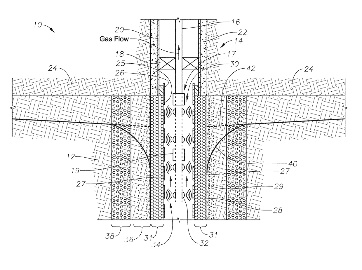
[0032]Shown in side sectional view in FIG. 1 is one embodiment of a microwave deliquification system 10. As shown, a hydrocarbon-bearing reservoir 12 includes a wellbore 14, which itself includes tubing 16, packer 18, a casing 20, and cement 22. The wellbore 14 proceeds through a cap rock 24 into the hydrocarbon-bearing reservoir 12. While in some embodiments the systems and methods of the present disclosure are used to reduce or remove condensates near the wellbore in a hydrocarbon-bearing reservoir by heating, the systems and methods can be used in other reservoir types for other applications. The systems and methods can be used for heating in oil reservoirs for heavy-oil and bitumen recovery with a single well process, also known as “huff-n-puff” (using steam injection), and for enhanced oil recovery displacement processes using multiple wells.

[0033]Still referring to FIG. 1, wellbore 14 further includes an open-hole liner 26, which proceeds downwardly into the wellbore 14 from t...


PUM

PropertyMeasurementUnit
temperatureaaaaaaaaaa

Abstract

Systems and methods for reducing or removing condensate blockage in a natural gas wellbore and a near-wellbore formation. Microwaves are used to heat a ceramic-containing material within a near-wellbore formation. Heat is transferred from the ceramic-containing material to the near-wellbore formation. Any gas condensate reservoirs in the near well-bore formation are heated, and condensed liquids accumulated around the wellbore are re-evaporated.

Description

PRIORITY CLAIM[0001]The present application is a non-provisional application claiming priority to provisional U.S. App. No. 62 / 157,237, filed May 5, 2015, the entire disclosure of which is incorporated here by reference.BACKGROUND[0002]1. Field[0003]The present disclosure relates to operations in a wellbore associated with the production of hydrocarbons. More specifically, the disclosure relates to systems and methods for reducing or removing condensate blockage in and around a natural gas wellbore.[0004]2. Description of the Related Art[0005]During production of natural gas from a wellbore, as the flowing bottomhole pressure declines to less than the dew-point pressure of the natural gas, heavier components of natural gas condense into liquid and dropout of the gas phase. Condensation of liquids results in near-wellbore formation damage (or blockage), which is caused by not only accumulation of condensed hydrocarbons, but also by the accumulation of formation water during the produ...

Claims


Application Information

Patent Timeline
Patent Type & Authority Patents(United States)
IPC IPC(8): E21B36/04E21B47/06H05B6/72H05B6/80E21B37/00E21B43/24
CPCE21B36/04E21B47/065H05B6/72H05B6/80H05B2206/045E21B37/00E21B43/2401E21B47/07
Inventor AYUB, MUHAMMADBATARSEH, SAMEEH I.HABIB, NABEEL S.
Owner SAUDI ARABIAN OIL CO
Why Eureka
Try Eureka