
Pressure range delimited valve with close assist

a technology of pressure range and valve body, applied in the field of valves, can solve the problems of destroying the well, affecting the gas recovery process, and presenting great challenges to the industry, and achieve the effect of enhancing the gas recovery

Inactive Publication Date: 2012-06-21
BOSLEY GAS ELEVATOR SYST
View PDF3 Cites 8 Cited by
  • Summary
  • Abstract
  • Description
  • Claims
  • Application Information

AI Technical Summary

Benefits of technology

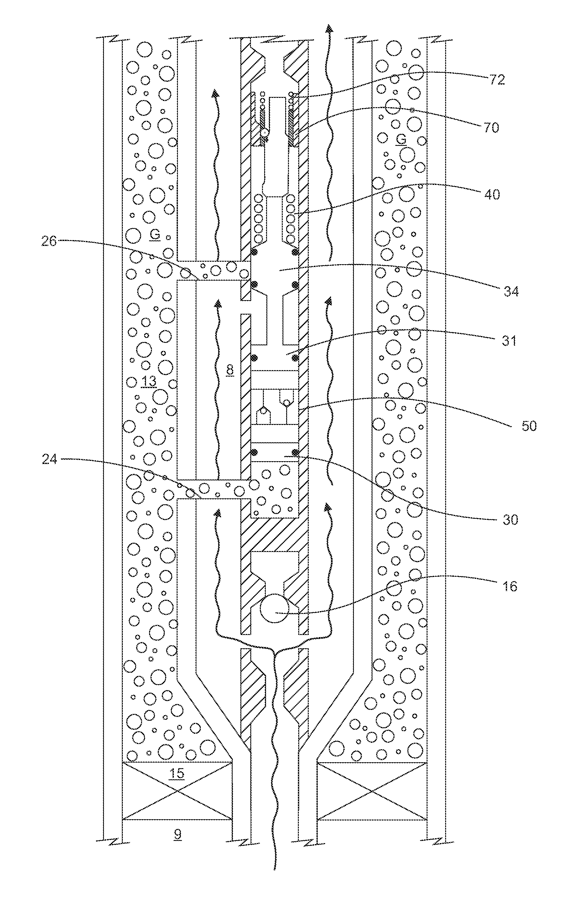
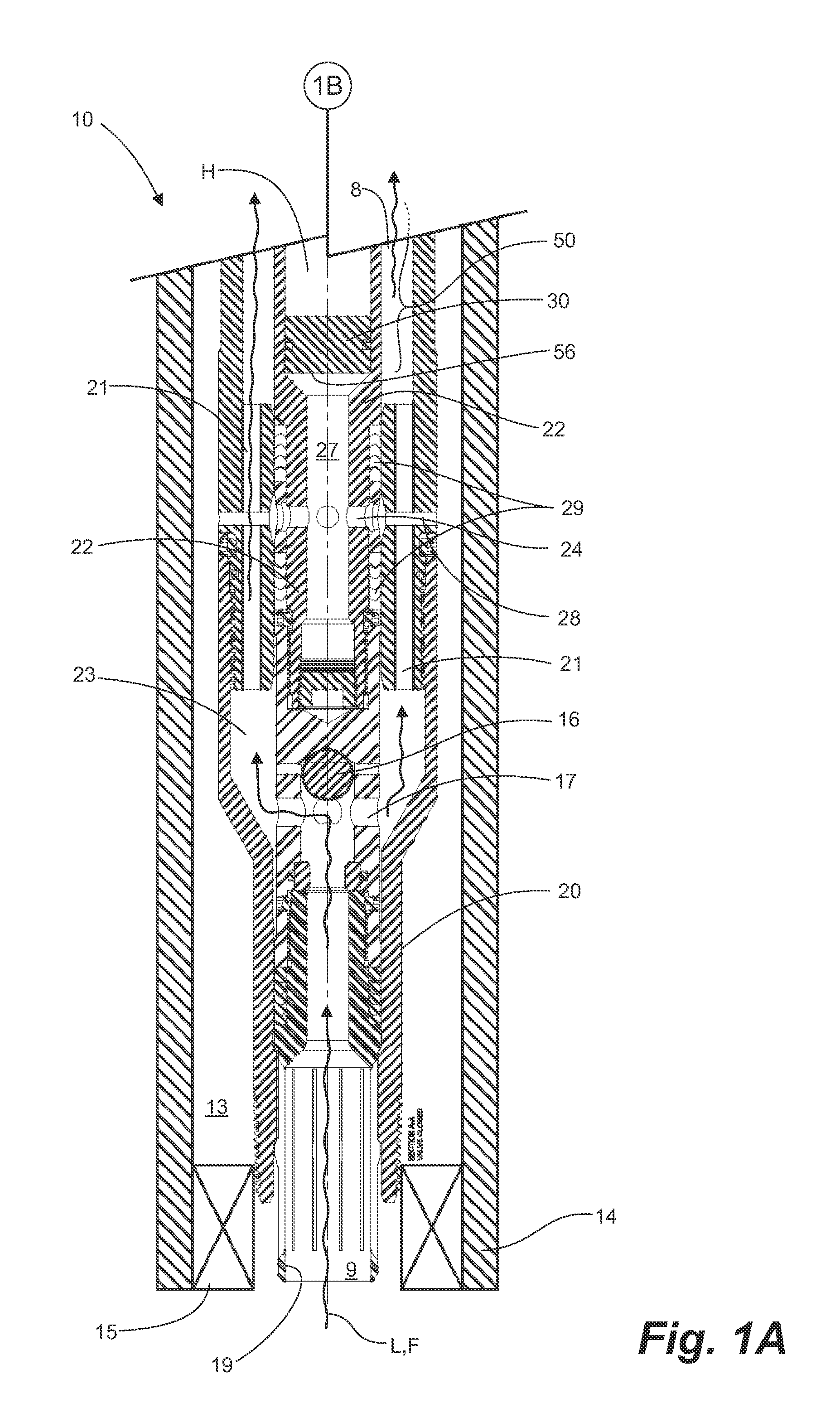
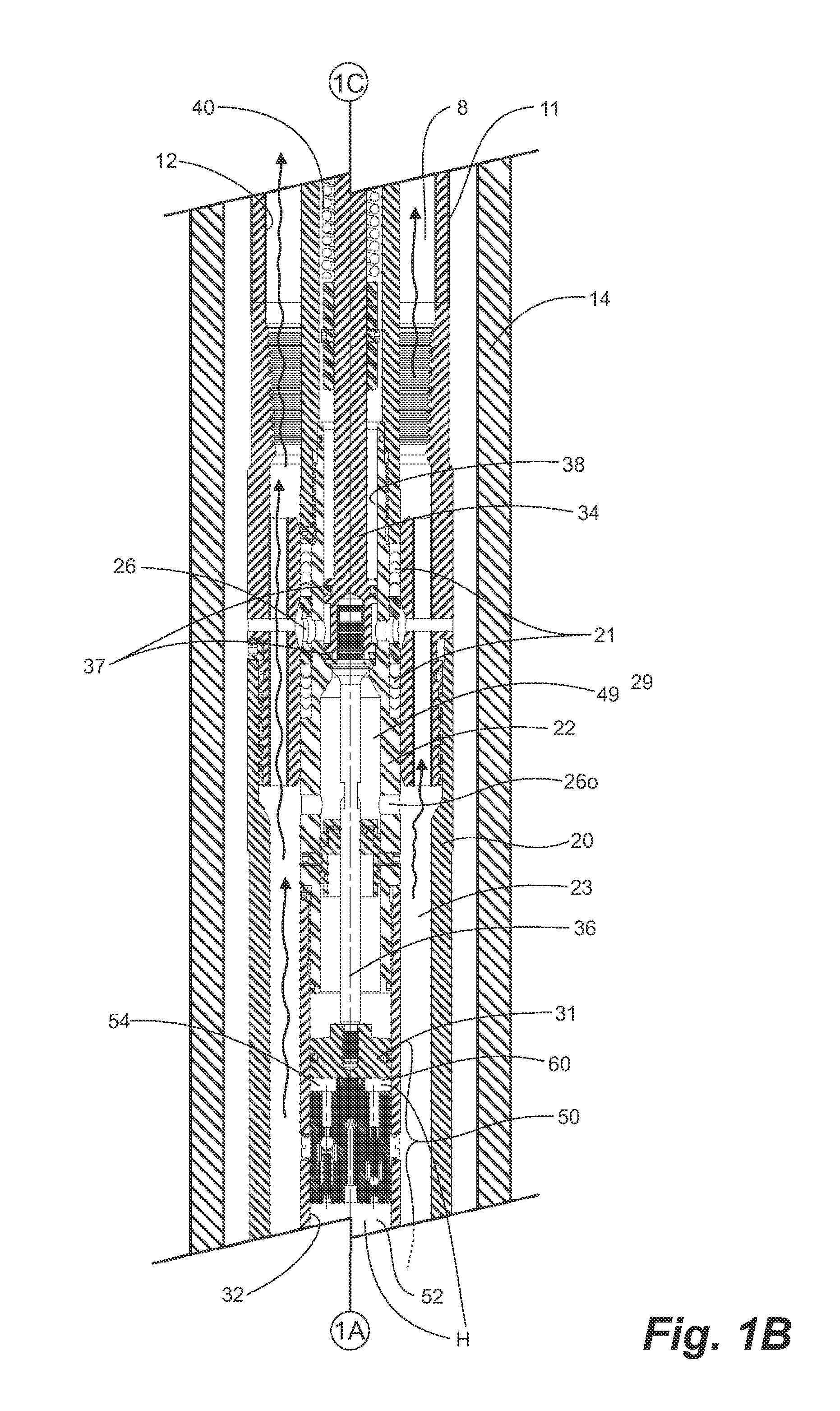
[0015]Therefore in a broad aspect, a system is provided for enhancing gas recovery from a wellbore which extends to a reservoir having diminished pressure. The wellbore has a tubing string therein. A packer is set above perforations in the tubing string and forms a wellbore annulus thereabove. Compressed gas pressurizes the wellbore annulus. Liquids accumulate in a bore of the tubing string as wellbore gas is produced therethrough to surface. The system comprises a one-way valve at a bottom of the tubing string for one-way fluid communication from the reservoir to the tubing string. A pressure-actuated valve is housed in the bore of the tubing string uphole from the one-way valve and forms a production annulus therebetween in fluid communication with the tubing annulus. The pressure-actuated valve comprises a valve body having a valve bore, inlet ports for fluid communication between the wellbore annulus and the valve bore; outlet ports in the valve body, spaced downhole from the inlet ports, for fluid communication between the valve bore and the production annulus; a plunger axially moveable in the valve bore, uphole from the inlet ports, for alternately blocking the inlet ports for preventing gas accumulating in the wellbore annulus from entering the valve body in a closed, production position; and unblocking the inlet ports for admitting gas from the wellbore annulus to the valve bore and flowing through the outlet ports to the production annulus for lifting accumulated fluids therein to surface in an open, lift position; a main spring operatively connected to the plunger for normally biasing the plunger to the production position; and a pressure-actuated pilot valve positioned in the valve bore and in continuous pressure communication with the wellbore annulus. When the pressure in the wellbore annulus exceeds a preset high pressure, the pilot valve opens to communicate the high pressure to the plunger for overcoming the biasing and moving the plunger from the production position to the open, lift position. When the pressure in the wellbore annulus is below a preset low pressure, the pilot valve releases the pressure acting at the plunger, allowing the plunger to be biased from the lift position to the closed, production position.

Problems solved by technology

More particularly in the production of hydrocarbons, particularly from gas wells, the accumulation of liquids, primarily water, has presented great challenges to the industry.
As the liquid builds at the bottom of the well, a hydrostatic pressure head is built which can become so great as to overcome the natural pressure of the formation or reservoir below, eventually “killing” the well.
To further complicate the process, the formation pressure typically declines over time.
Once the pressure has declined sufficiently so that production has been adversely affected, or stopped entirely, the well might be abandoned or rehabilitated.
Unfortunately, in situations where the formation pressure has declined significantly, it can take many hours to build sufficient pressure to blowdown or lift the liquids, reducing the hours of production.
In order to supply the large volumes of compressed gas required to perform conventional gas lift, large and expensive systems, requiring large amounts of energy, are required.
Complex crossover elements or multiple standing valves are required for implementations using two tubing strings, which add to the maintenance costs and associated problems.
Conventional pressure-actuated valves however require complex control mechanisms to permit maintaining the valve in a closed position for sufficient time to build the necessary energy in the annulus to lift the liquids and then to remain open for sufficient time to permit the energy to be discharged into the production tubing for lifting the fluids to surface.
Typically, such valves are only capable of maintaining a pressure differential of about 50 psi, which is largely insufficient to permit enough gas to sweep liquids to surface.

Method used


Image

  • Pressure range delimited valve with close assist
  • Pressure range delimited valve with close assist
  • Pressure range delimited valve with close assist

Examples


Embodiment Construction

[0030]As described herein, valve 10, is actuated by a high pressure to open and biased under lower pressures to close. Valve closing or kicker means are provided for assisting the valve to close fully.

[0031]With reference to FIGS. 1A-1C and 1D-1F, it is convenient to illustrate the operation of one embodiment of the valve 10 for the control of production fluids F and removal of accumulated liquids L from a wellbore 9. The wellbore 9 is cased with a casing string 14 and a tubing string 11 extends down the cased wellbore 9, having a downhole end located for receipt of the production fluids F. The valve 10 is located in a bore 12 of the downhole end of the tubing string 11.

[0032]A wellbore annulus 13 is formed between the tubing string 11 and the casing string 14. In this embodiment a packer 15, shown in a fanciful schematic form only and with non-pertinent downhole components of the valve or downhole assembly omitted, seals the wellbore annulus 13 so that production fluids F from the ...


PUM


Abstract

A pressure-actuated valve fit to a tubing string for alternately closing to communicate fluids from a wellbore to the tubing string and opening to communicate fluids from a wellbore annulus to the tubing string. The valve is particularly useful for lifting liquids which accumulate in the tubing string when the reservoir has a diminished pressure. In this case, gas is accumulated in the wellbore annulus and when the valve is opened the gas enters the valve and is directed to the tubing string for lifting the liquids. The valve is closed by a spring and has a closing-assist which applies an additional force to the spring to ensure the valve is fully closed.

Description

CROSS-REFERENCE TO RELATED APPLICATIONS[0001]This application claims the benefit of U.S. provisional application 61 / 424,928, filed Dec. 20, 2010, the entirety of which is incorporated herein by reference.FIELD OF THE INVENTION[0002]Embodiments of the invention relate to valves which are actuated by pressure differentials across the valve and more particularly to valves which are operable at high pressure differentials, which can be actuated to shift reliably to the closed position and which are particularly suitable for unloading accumulated water from gas production wellbores.BACKGROUND OF THE INVENTION[0003]Valves are known which operate to open or close due to a pressure differential across the valve for a variety of uses. Conventional pressure-actuated valves typically open at a first pressure and dynamically close as the pressure drops, throttling the flow through the valve. Further, many conventional valves must be reset other than by pressure, relying on some electrical or ot...

Claims


Application Information

Patent Timeline
Patent Type & Authority Applications(United States)
IPC IPC(8): E21B34/00
CPCE21B43/123E21B34/085E21B43/13
Inventor MITCHELL, BRUCEBOSLEY, GORDON
Owner BOSLEY GAS ELEVATOR SYST
Learn More