Air spring structure

a technology of air springs and springs, which is applied in the direction of cycle springs, shock absorbers, cycle equipment, etc., can solve the problems of complicated manufacture and configuration of cylinders

Active Publication Date: 2018-09-25
SHOWA CORP
View PDF15 Cites 14 Cited by
  • Summary
  • Abstract
  • Description
  • Claims
  • Application Information

AI Technical Summary

Benefits of technology

[0009]The present disclosure has been developed in view of the above-described problem. An object of the present disclosure is to provide an air spring structure that allows the internal pressures of the first end chamber and the second end chamber defined in the cylinder to be made equal using a simple configuration.
[0011]The aspect of the present disclosure is effective for allowing the internal pressures of the first end chamber and the second end chamber defined in the cylinder to be made equal using a simple configuration.

Problems solved by technology

This disadvantageously makes manufacture and configuration of the cylinder complicated.

Method used


Image

  • Air spring structure
  • Air spring structure
  • Air spring structure

Examples


embodiment 1

[0023](Embodiment 1)

[0024](1-1. General Configuration of the Front Fork 4)

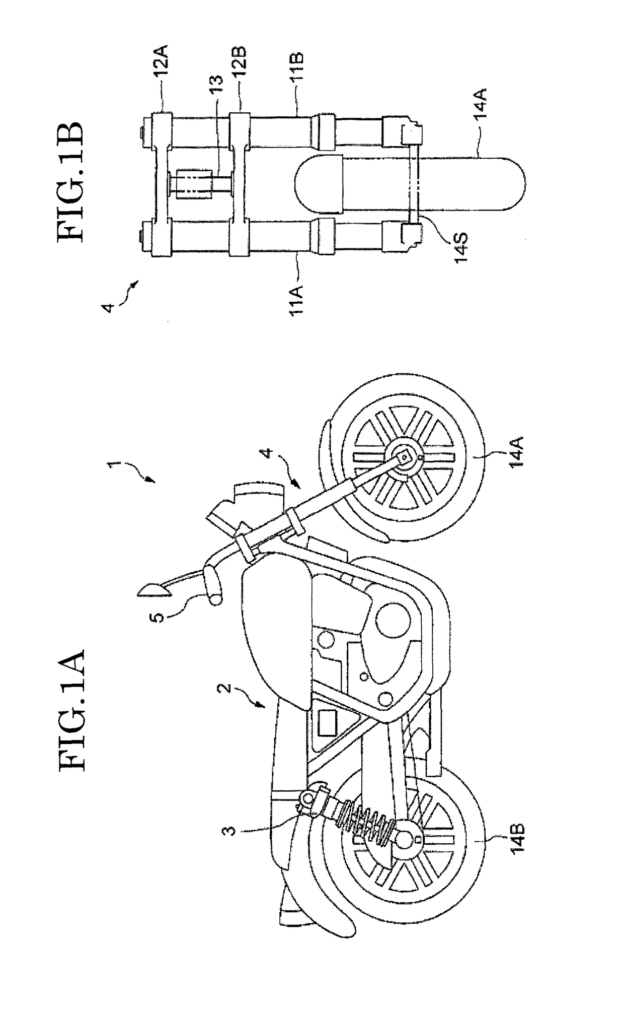
[0025]FIG. 1A is a drawing depicting a configuration of a motorcycle 1 in which a front fork 4 according to Embodiment 1 is mounted. FIG. 1B is a drawing depicting a configuration of the front fork 4.

[0026]The motorcycle 1 depicted in FIG. 1A includes a vehicle body 2, a front wheel 14A attached to an axle arranged in the front of the vehicle body 2, a rear wheel 14B attached to an axle arranged in the rear of the vehicle body 2, a rear suspension 3 that connects the vehicle body 2 and the rear wheel 14B together, the front fork 4 that connects the vehicle body 2 and the front wheel 14A together, and a handlebar 5 that allows the motorcycle 1 to be steered.

[0027]The front fork 4 couples the front wheel 14A to the vehicle body 2 of, for example, a two-wheeled vehicle or a tricycle to cushion impact and to transmit steering of the handlebar 5 to the front wheel 14A. In the present embodiment, as depicted in FIG....

embodiment 2

[0097](Embodiment 2)

[0098](2-1. Configuration of the Cylinder 21A)

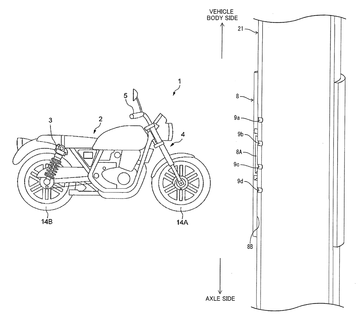
[0099]FIG. 9 is a partial perspective view of the cylinder 21A to which the communication member 8 of the first fork leg 11A according to Embodiment 2 is attached as seen from an inner side of the cylinder 21A. FIG. 10 is a schematic view illustrating a relation between the communication path 8A formed in the communication member 8 and communication holes 9a to 9g formed in the cylinder 21A of the first fork leg 11A according to Embodiment 2. The same components as those which are described above with reference to FIG. 6 are denoted by the same reference numerals. Detailed descriptions of these components will not be repeated.

[0100]The four communication holes 9a to 9d are formed in the peripheral surface of the cylinder 21A at intervals each equal to the length L1 along the axial direction. On the peripheral surface of the cylinder 21A, at a distance from the communication holes 9a to 9d in the circumferential direct...

embodiment 3

[0110](Embodiment 3)

[0111](Variation of Arrangement of the Communication Holes)

[0112]As shown in FIG. 7, perfect alignment of the four communication holes 9a to 9d is no necessarily required in line along the major axis of the cylinder 21. Even if the positions of some of the communication holes 9a to 9d are slightly displaced in the circumferential direction, no problem occurs when the communication path 8A in the communication member 8 allows two of the communication holes 9a to 9d to communicate with each other.

[0113]For the arrangement of the seven communication holes 9a to 9g depicted in FIG. 11, perfect alignment of the communication holes 9a to 9d and the communication holes 9e to 9g is not necessarily required in line along the major axis of the cylinder 21A.

[0114]A major axis of the communication path 8A in the communication member 8 need not be formed parallel to the major axis of the cylinder 21, 21A. The communication path 8A may be formed in any manner so long as the co...


PUM


Abstract

An air spring structure has a first communication hole formed in a peripheral surface of a cylinder and a second communication hole formed in the peripheral surface at a position closer to an axle than the first communication hole. A piston has a sliding portion that comes into contact with an inner peripheral surface of the cylinder and partitions the cylinder into an inner chamber and a balance chamber. The sliding portion has an axial length shorter than an axial length between the first communication hole and the second communication hole. A communication member has a communication path formed so as to pass through the first communication hole and the second communication hole to allow the inner chamber and the balance chamber to communicate with each other.

Description

CROSS-REFERENCE TO RELATED APPLICATIONS[0001]The present application claims priority under 35 U.S.C. § 119 to Japanese Patent Application No. 2016-062592, filed Mar. 25, 2016. The contents of this application are incorporated herein by reference in their entirety.BACKGROUND[0002]Field[0003]The present disclosure relates to an air spring structure, and in particular, to an air spring structure provided in a front fork installed on a front wheel side of a two-wheeled vehicle to absorb vibration from road surfaces that is input to a front wheel.[0004]Related Art[0005]As a related art, an air spring is known which has a cylinder with a first end that is a closed end, a rod with a leading end thereof inserted through the cylinder via a second end thereof so as to move in and out of the cylinder, a piston that is housed in the cylinder so as to be able to slide and that is held at the leading end of the rod, and a first end chamber and a second end chamber defined by the piston in the cyl...

Claims


Application Information

Patent Timeline
Patent Type & Authority Patents(United States)
IPC IPC(8): F16F9/48B62K25/08F16F9/02F16F9/346B62K25/04
CPCB62K25/08F16F9/0209F16F9/346F16F9/0218B62K2201/08B62K2025/044
Inventor YOSHIDA, KOJIRO
Owner SHOWA CORP
Why Eureka
Try Eureka