Air-suspension system

a suspension system and suspension tube technology, applied in the direction of shock absorbers, mechanical equipment, transportation and packaging, etc., can solve the problems of difficult assembly line production integration of work sequence, difficulty in fitting and adjusting control valves or actuating devices, and impaired operability of external level control valves and thus of vehicles

Inactive Publication Date: 2001-12-25
ZF FRIEDRICHSHAFEN AG
View PDF8 Cites 42 Cited by
  • Summary
  • Abstract
  • Description
  • Claims
  • Application Information

AI Technical Summary

Problems solved by technology

A basic problem with the disclosed system is that it is difficult to fit and adjust the control valve or a actuating device for the control valve so that a certain switching position of the control valve is set as a function of a loading state or a stroke position of the air spring.
However, this sequence of work is difficult to integrate in an assembly line production.
Furthermore, the operability of the external level control valve and thus of the vehicle may be impaired by dirt or moisture when using an air-sprung vehicle in difficult terrain.
The end position may also be implemented via a stop independently of the rotary-slide valve, but the components would then be more complicated.

Method used


Image

  • Air-suspension system
  • Air-suspension system
  • Air-suspension system

Examples


Embodiment Construction

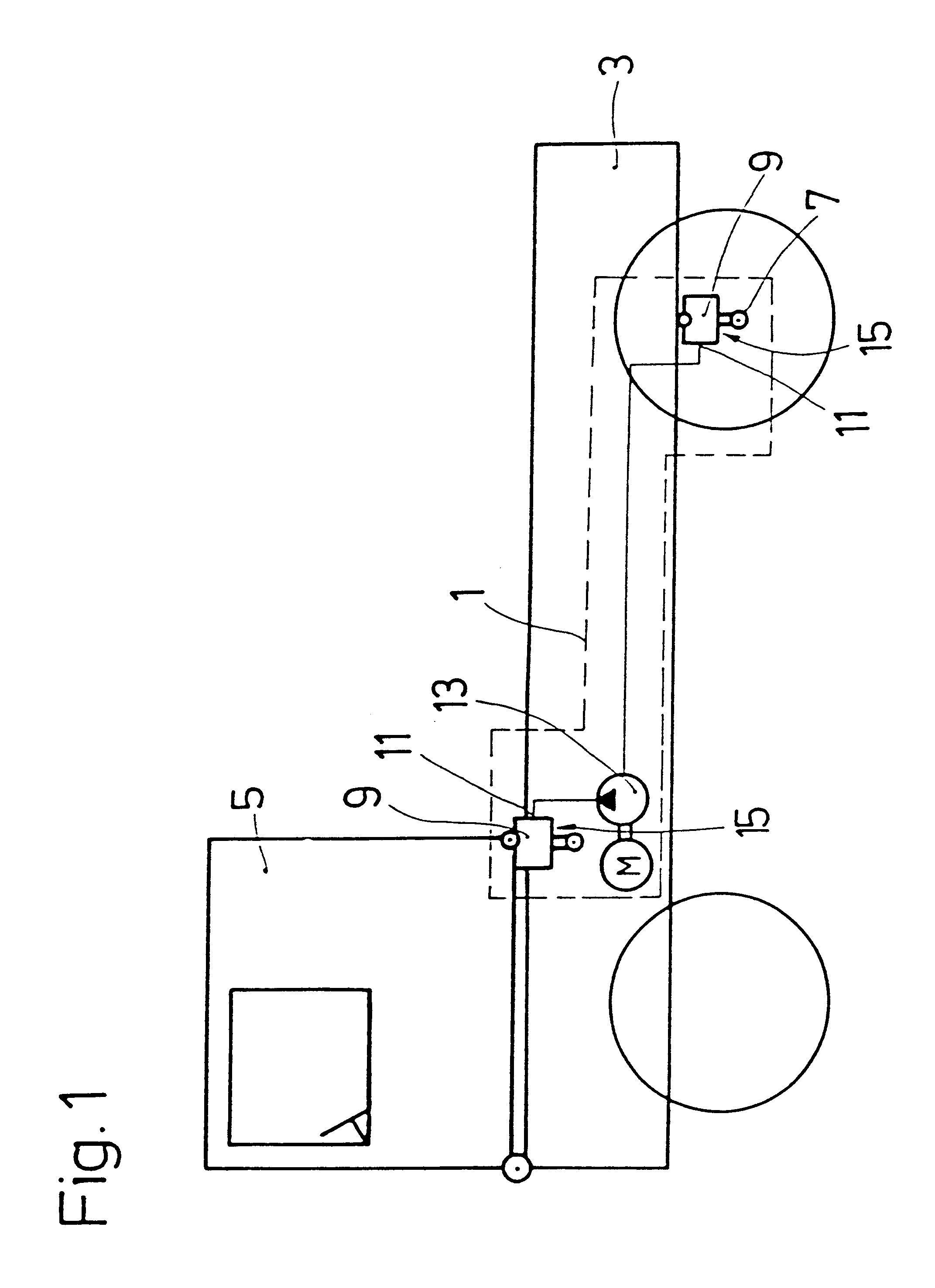
FIG. 1 shows an installation arrangement for an air-suspension system 1 between a chassis 3 and a vehicle component such as, for example, a driver's cab 5 or a vehicle axle 7 mounted for movement along an oscillatory path relative to the chassis 3. At least one air spring 9 is connected to a pressure source 13 via a supply connection 11 via a control valve 15, the control valve 15 being part of the air spring 9. The supply may be effected by a compressor unit.

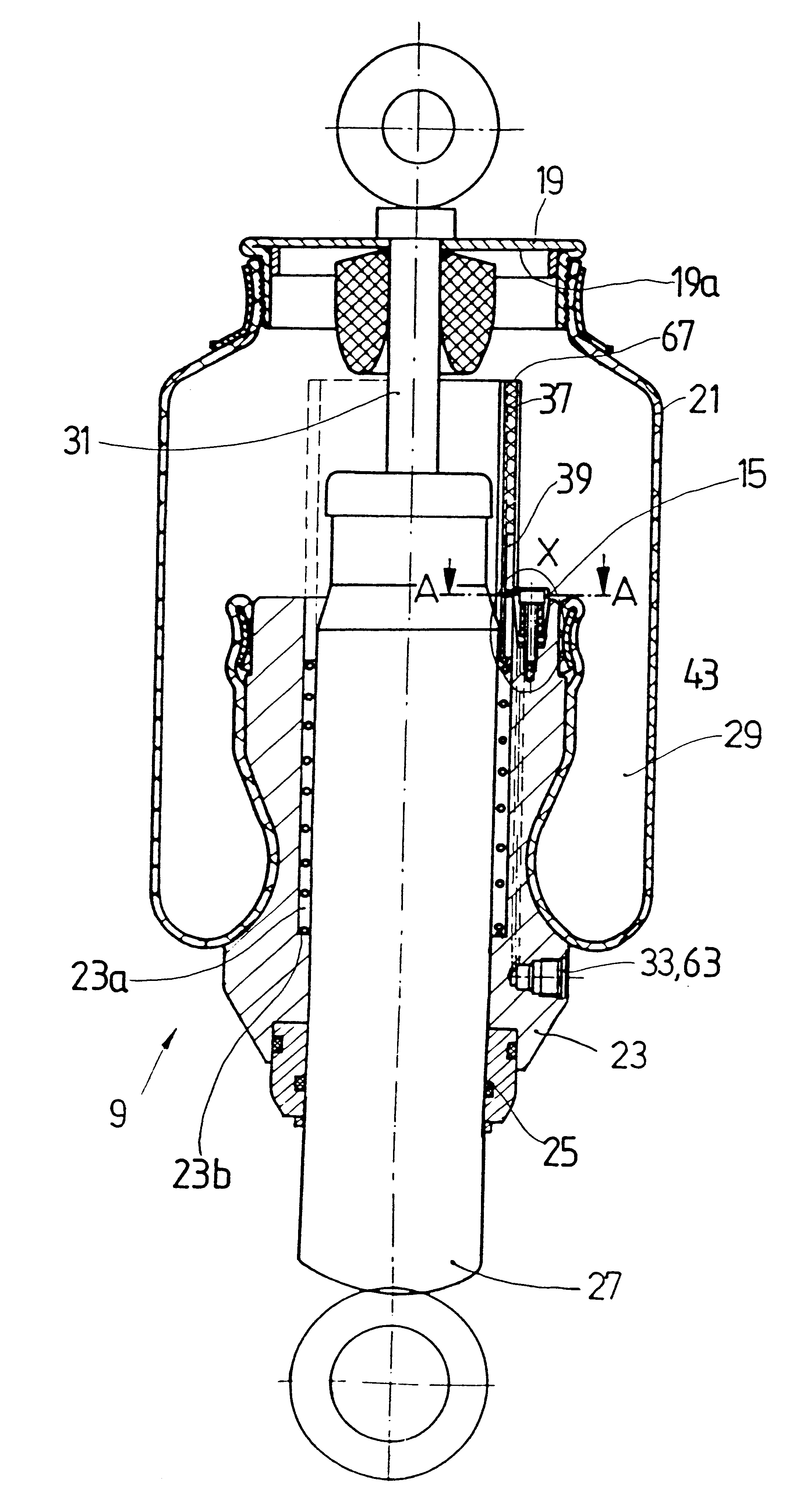
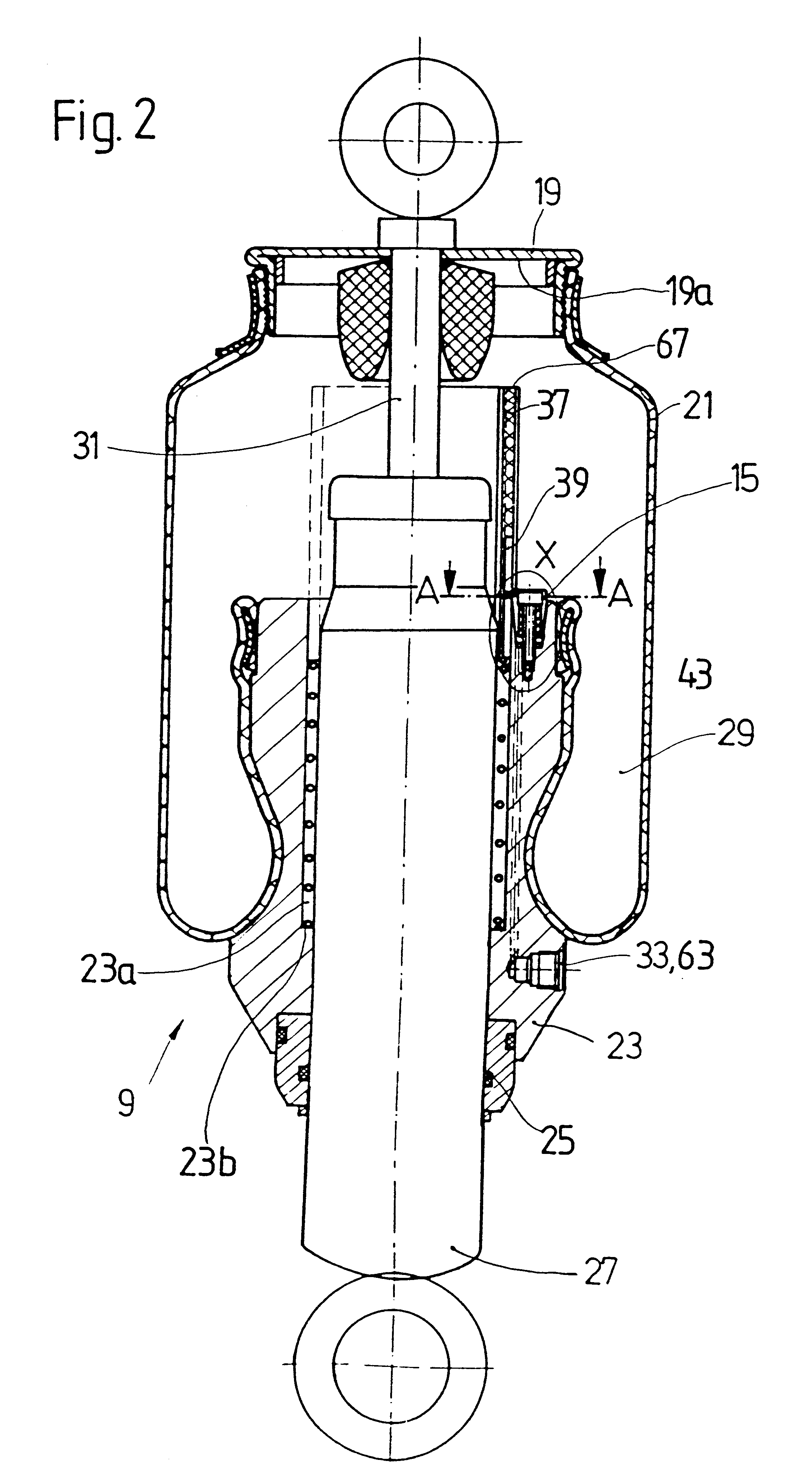
The air spring 9 is shown in FIG. 2 and comprises a piston rod 31 axially movably mounted in a reservoir tube 27. An outer tube 19 is connected to the piston rod 31 and is also fastened to one end of a spring bellows 21. The other end of the spring bellows 21 is clamped in place on a rolling tube 23 which is mounted on the reservoir tube 27 and sealed off from the reservoir tube 27 by seals 25. A spring space 29 which is pressurized is defied by the outer tube 19 and the spring bellows 21 which is sealed relative to the reservo...


PUM


Abstract

An air-suspension system has at least one air spring arranged between a chassis and a vehicle component mounted relative to said chassis for movement along an oscillatory path. A control valve is arranged inside the air spring and has control positions for feeding, blocking and discharging compressed air in the air spring. The control valve is activated via a control element also arranged inside the air spring. A guideway of the control element acts on one of an outer tube air-spring subassembly and a rolling tube air-spring subassembly which are movable relative to one another. The control valve is designed as a rotary-slide valve and is activated via the guideway and a rotary-slide valve body. The guideway of the control element is shorter than the stroke length of the air spring, the one of the subassemblies which actuates the control element being in releasable operative connection with the control element. The releasable operative connection is restricted only to a section of the stroke travel between the two air-spring subassemblies of outer tube or rolling tube.

Description

1. Field of the InventionThe invention relates to an air-suspension system having at least one air spring for installation between a chassis and a vehicle component mounted for oscillating along an oscillatory path relative to the chassis, the air spring having a control valve for feeding, blocking, or discharging compressed air in the air spring.2. Description of the Related ArtAn air suspension system is disclosed, for example, in German reference DE 33 47 435 A1 having an air spring connectable between a chassis of a vehicle and a vehicle component mounted for oscillating along an oscillation path relative to the chassis. A control valve is arranged for feeding, blocking, or discharging compressed air in the air spring. A basic problem with the disclosed system is that it is difficult to fit and adjust the control valve or a actuating device for the control valve so that a certain switching position of the control valve is set as a function of a loading state or a stroke position...

Claims


Application Information

Patent Timeline
Patent Type & Authority Patents(United States)
IPC IPC(8): B60G17/048B60G17/04B62D33/06F16F9/02F16F9/05
CPCB60G17/0485B62D33/0608F16F9/05B60G2202/152B60G2204/126B60G2204/162B60G2500/20B60G2500/2042B60G2500/2044
Inventor GILSDORF, JOACHIMHEROLD, WINFRIED
Owner ZF FRIEDRICHSHAFEN AG
Why Eureka
Try Eureka