Integrated manifold system for controlling an air suspension

a manifold system and air suspension technology, which is applied in the direction of diaphragm valves, engine diaphragms, operating means/releasing devices of valves, etc., can solve the problems of limiting the usable complex air suspension systems, and many difficulties of manifold systems such as those described above, so as to increase the space on the circuit board, facilitate manufacturing, and cost-effective

Active Publication Date: 2014-12-09
AIR ELEVATOR
View PDF43 Cites 41 Cited by
  • Summary
  • Abstract
  • Description
  • Claims
  • Application Information

AI Technical Summary

Benefits of technology

[0007]The present invention provides a manifold system that maximizes space for the circuit board while enabling efficient control of multiple pneumatic devices.
[0011]The configuration of the solenoid, or multiple solenoids, positioned parallel to the manifold and the circuit board increases the amount of space for the circuit board. In addition, the utilization of the supply port for transporting both the pressurized air to the service port and the exhausted air to an exhaust port can reduce the number of ports that are required in the manifold, making the manifold easier to manufacture, and enabling the manifold to be formed by more cost effective methods, such as injection molding.

Problems solved by technology

As air suspension systems become more complex, manufacturers have utilized integrated manifold systems to control the air flow between the compressor and the air springs.
Manifold systems such as those described above suffer from a variety of difficulties.
First, the perpendicular orientation of the solenoids with respect to the manifold blocks limits the area over which the circuit board can be mounted as the circuit board must be constrained to the size of the vertical ends of the solenoids to prevent it from extending beyond the edges of the manifold block.
Second, the vertical orientation of the solenoids limits the usable space on the circuit board, because the area of the circuit board immediately above each solenoid must be free from components to allow enough space for the solenoid.
The combination of (1) limited space on the manifold for mounting the circuit board and (2) limited usable space on the circuit board limits the amount of components that can be attached to the circuit board for operating and monitoring the suspension system, and often requires the use of multiple, stacked circuit boards.
In addition, the vertical, direct acting solenoids require many ports to be formed into the manifold blocks, which can result in the need for multiple, stacked manifold blocks and can require tedious manufacturing work to form ports with the necessary depth.

Method used


Image

  • Integrated manifold system for controlling an air suspension
  • Integrated manifold system for controlling an air suspension
  • Integrated manifold system for controlling an air suspension

Examples


second embodiment

IV. Second Embodiment

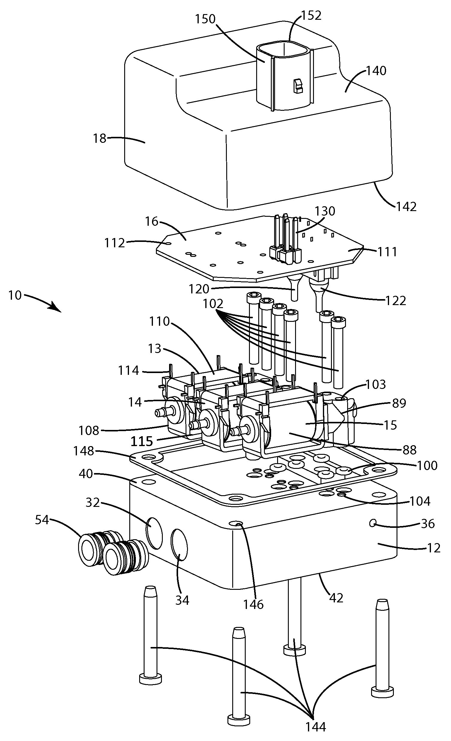
[0047]A second embodiment of the manifold system is shown in FIGS. 10-21 and generally designated 1010. Similar to the first described embodiment, the manifold system 1010 generally includes a manifold block 1012, a plurality of solenoids 1014 mounted on the manifold 1012, a circuit board 1016 mounted to the solenoids 1014 or the manifold 1012, and a cover 1018 enclosing the solenoids 1014. This embodiment varies from the first described embodiment in that this embodiment includes poppet valves instead of direct acting valves. The poppet valves include poppet assemblies 1020 that can be moved by the solenoids to open or close the service ports, exhaust port and the outlet ports. Poppet valves enable the manifold to control greater volumes of high pressure fluid with relatively low solenoid power.

[0048]The manifold block 1012 generally includes an upper surface 1022, a lower surface 1024, a front surface 1026, a rear surface 1028, a right side surface 1030 and a ...


PUM

PropertyMeasurementUnit
diameteraaaaaaaaaa
longitudinal lengthaaaaaaaaaa
lengthaaaaaaaaaa

Abstract

An integrated manifold system maximizes space for the circuit board while enabling efficient control of one or more pneumatic devices. The manifold system includes a manifold block, a solenoid valve attached to the manifold block, and a circuit board for controlling the solenoid and other components of an air suspension system. The manifold block includes at least one service port for connecting to a pneumatic device such as an air spring, and a supply port for connecting to a compressor. The solenoid valve is mounted to the manifold block with its longitudinal length being generally parallel to the service port. The circuit board is mounted adjacent to the solenoid valve and oriented generally parallel to the solenoid and service port. A cover encloses the solenoid valve and the circuit board. In one embodiment, the solenoid valve is in fluid communication with the supply port. The solenoid valve is uniquely associated with the service port.

Description

BACKGROUND OF THE INVENTION[0001]The present invention relates to vehicle air suspension systems, and more particularly to an integrated manifold system for selectively controlling the components of an air suspension system.[0002]Air suspension systems are well known for providing a softer, more comfortable ride for a vehicle. Other common applications for air suspension systems include: raising or lowering a vehicle; leveling a vehicle that is under a load; leveling recreational vehicles parked on inclined surfaces; and altering the performance characteristics of a vehicle. Air suspension systems may be installed on a vehicle by the original equipment manufacturer, or they may be purchased as aftermarket products that are substitutes or supplements for convention coil spring suspensions.[0003]Common air suspension systems typically include one or more pneumatic devices, such as air springs, connected between the vehicle axles and the vehicle chassis. Pressurized air from a compress...

Claims


Application Information

Patent Timeline
Patent Type & Authority Patents(United States)
IPC IPC(8): F15B13/04F16K1/00F15B13/00F15B13/08
CPCF15B13/0814F15B13/0853Y10T137/877Y10T137/87169Y10T137/87885Y10T29/49002
Inventor COOMBS, JOSHUA D.MULDER, AARON
Owner AIR ELEVATOR
Why Eureka
Try Eureka