Antenna element, feed probe; dielectric spacer, antenna and method of communicating with a plurality of devices

a technology of feed probes and antennas, applied in the field of antenna elements and feed probes, can solve problems such as requiring an unacceptably large number of antennas at each si

Active Publication Date: 2006-10-19
COMMSCOPE TECH LLC
View PDF35 Cites 38 Cited by
  • Summary
  • Abstract
  • Description
  • Claims
  • Application Information

AI Technical Summary

Benefits of technology

[0011] Preferably the low frequency ring element has a minimum outer diameter b, a maximum inner diameter a, and the ratio b / a is less than 1.5. A relatively low b / a ratio maximizes the space available in the center of the ring for locating the high band element, for a given outer diameter.
[0035] Forming the spacer portion and support portion from a single piece enables the spacer to be manufactured easily and cheaply.

Problems solved by technology

To provide dedicated antennas for each system would require an unacceptably large number of antennas at each site.

Method used


Image

  • Antenna element, feed probe; dielectric spacer, antenna and method of communicating with a plurality of devices
  • Antenna element, feed probe; dielectric spacer, antenna and method of communicating with a plurality of devices
  • Antenna element, feed probe; dielectric spacer, antenna and method of communicating with a plurality of devices

Examples


Embodiment Construction

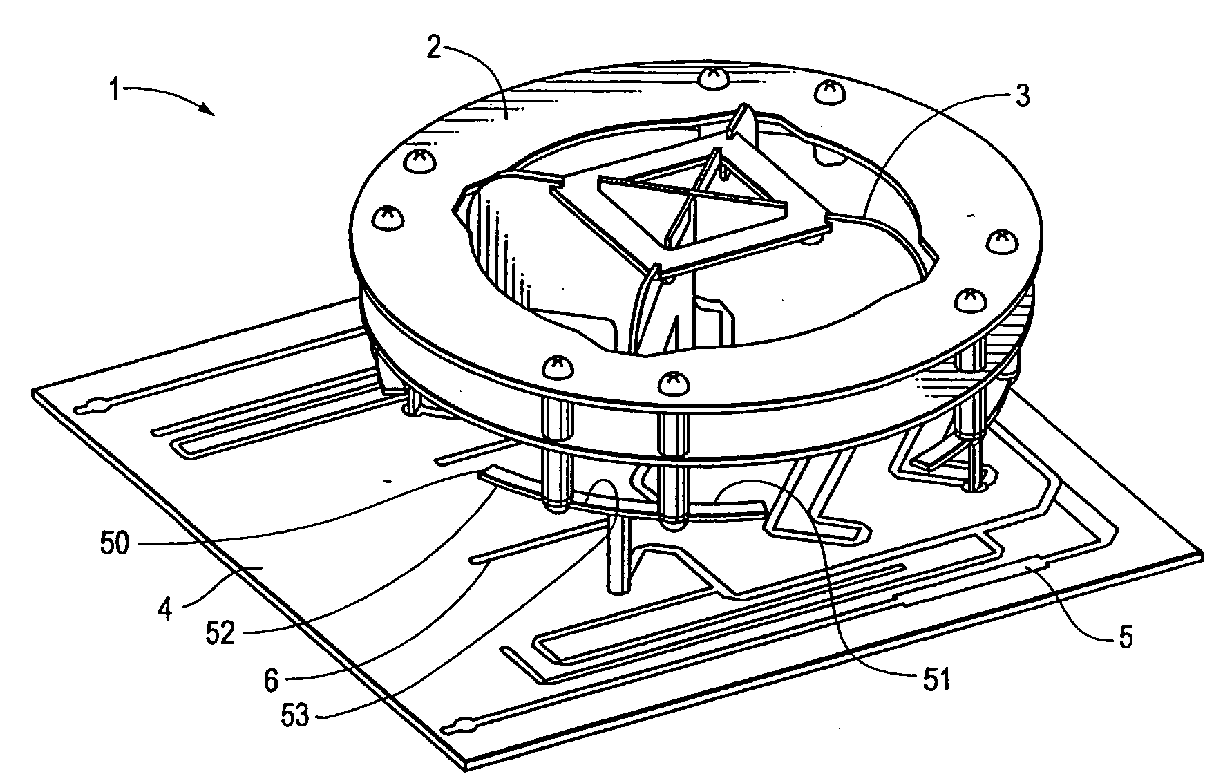
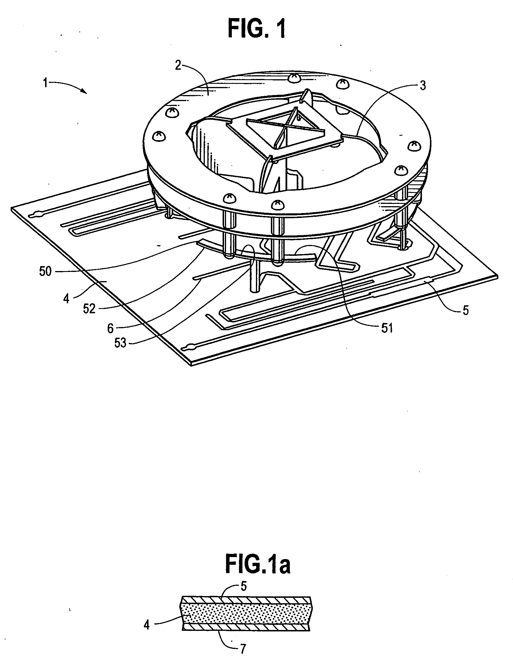
[0073]FIG. 1 shows a single antenna module 1, comprising a single low frequency Microstrip Annular Ring (MAR) 2 and a single high frequency Crossed Dipole Element (CDE) 3 centred in the MAR 2. The MAR 2 and CDE 3 are mounted on a printed circuit board (PCB). The PCB comprises a substrate 4 which carries a microstrip feedline network 5 coupled to the MAR 2, and a microstrip feedline network 6 coupled to the CDE 3. As shown in FIG. 1a (which is a cross section through part of the PCB), the other face of the substrate 4 carries a ground plane 7. The MAR 2 and CDE 3 are shown separately in FIGS. 2a-c and FIGS. 3a-f respectively.

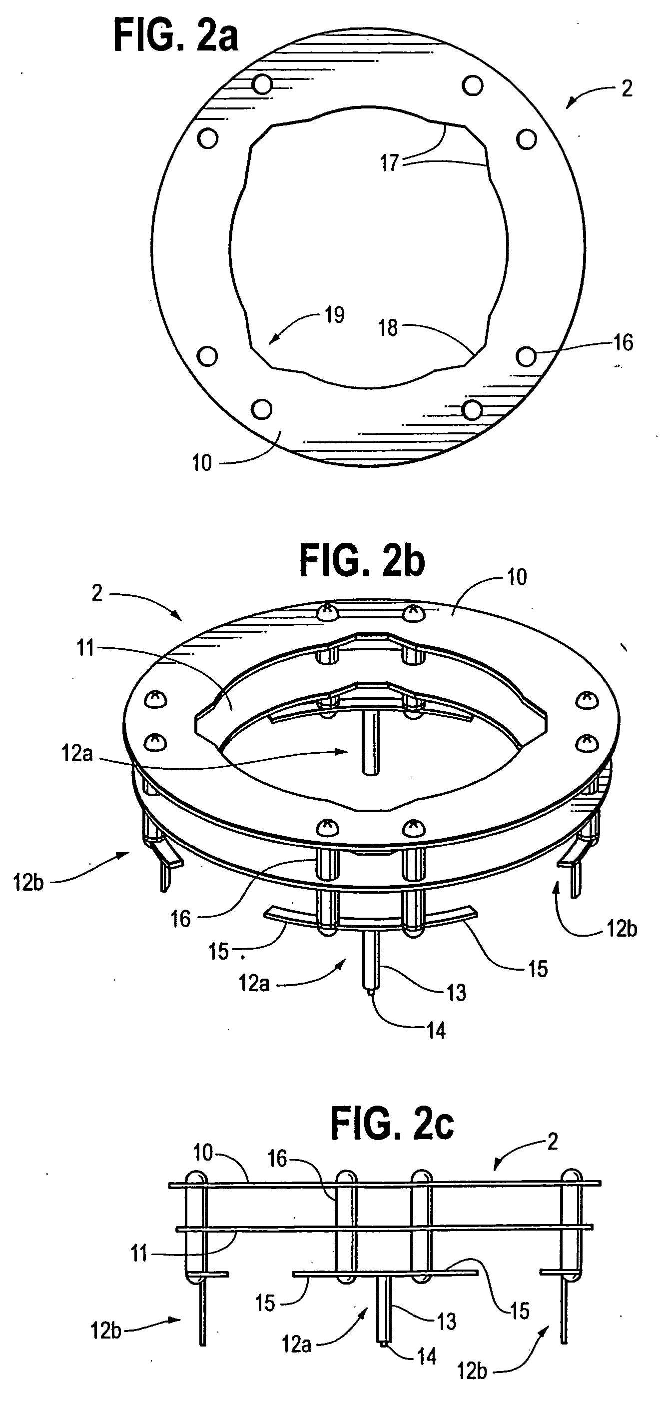
[0074] Referring to FIGS. 2a-c, the MAR 2 comprises an upper ring 10, lower ring 11, and four T-probes 12a, 12b. Each T-probe 12a, 12b is formed from a single T-shaped piece of metal with a leg 13 and a pair of arms 15. The leg 13 is bent down by 90 degrees and is formed with a stub 14 which passes through a hole in the PCB and is soldered to the feed network 5....


PUM


Abstract

A multiband base station antenna for communicating with a plurality of terrestrial mobile devices is described. The antenna including one or modules, each module including a low frequency ring element; and a high frequency dipole element superposed with the low frequency ring element. The element includes a ground plane; and a feed probe directed away from the ground plane and having a coupling part positioned proximate to the ring to enable the feed probe to electromagnetically couple with the ring. A dielectric clip provides a spacer between the feed probe and the ring, and also connects the ring to the ground plane. An antenna element is also described including a ring, and one or more feed probes extending from the ring, wherein the ring and feed probe(s) are formed from a unitary piece.

Description

CROSS-REFERENCE TO RELATED APPLICATIONS [0001] This application claims the benefit of priority from provisional patent application Ser. No. 60 / 482,689, filed Jun. 26, 2003, entitled Antenna Element, Multiband Antenna, And Method Of Communicating With A Plurality Of Devices. Provisional patent application Ser. No. 60 / 482,689, is incorporated herein by reference in its entiretyFIELD OF THE INVENTION [0002] The present invention relates in its various aspects to an antenna element, a proximity-coupling feed probe for an antenna; a dielectric spacer for an antenna; an antenna (which may be single band or multiband), and a method of communicating with a plurality of devices. The invention is preferably but not exclusively employed in a base station antenna for communicating with a plurality of terrestrial mobile devices. BACKGROUND OF THE INVENTION [0003] In some wireless communication systems, single band array antennas are employed. However in many modern wireless communication systems...

Claims


Application Information

Patent Timeline
Patent Type & Authority Applications(United States)
IPC IPC(8): H01Q21/26H01Q1/24H01Q9/04H01Q9/16H01Q13/08H01Q21/08H01Q21/12H01Q21/24H01Q21/28
CPCH01Q1/246H01Q9/0414H01Q9/0457H01Q21/28H01Q9/0464H01Q3/16H01Q9/285H01Q19/10
Inventor BISIULES, PETER JOHNYANG, CHING-SHUN
Owner COMMSCOPE TECH LLC
Why Eureka
Try Eureka