Electromechanical Module Configuration

a technology of electronic components and configuration, applied in the field of wearable electronic devices, can solve problems such as reducing manufacturing capability efficiency, and achieve the effects of reducing manufacturing costs, inventory costs and schedule time, and facilitating modification, change and/or enhancement of functionalities

a technology of electronic components and configuration, applied in the field of wearable electronic devices, can solve problems such as reducing manufacturing capability efficiency, and achieve the effects of reducing manufacturing costs, inventory costs and schedule time, and facilitating modification, change and/or enhancement of functionalities

US20100220559A1Inactive Publication Date: 2010-09-02TIMEX CORP

Image

  • Electromechanical Module Configuration
  • Electromechanical Module Configuration
  • Electromechanical Module Configuration

Examples


Embodiment Construction

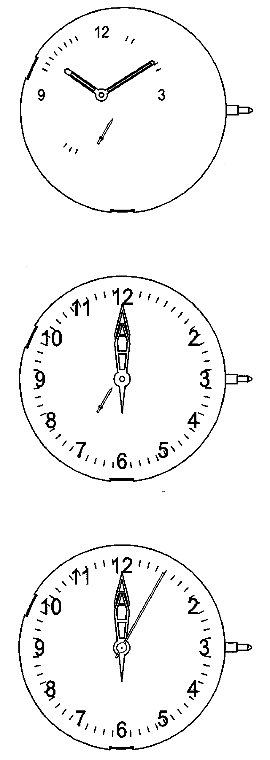
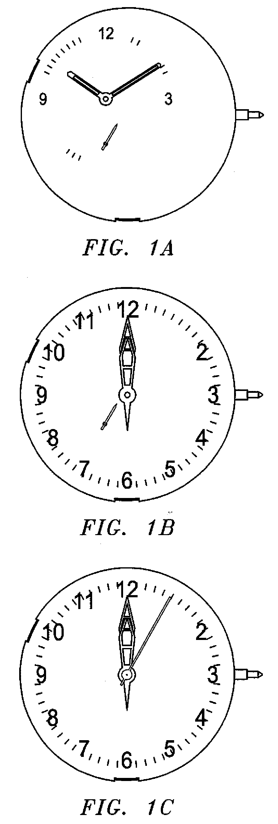
[0057]Reference is first made to FIGS. 1-11 in combination with the following, for a disclosure of just some of the functional capabilities achieved by the present invention. For example, the present invention provides for:

a. Time Telling: conventional time telling functions of a movement (hours, minutes, and seconds), with additional capabilities such as:[0058]time shown in the “Glashütte position”[0059]time shown with conventional center and off-center mounted hour, minute, and sweep second hands[0060]optional sub-second capability[0061]optional AM / PM indicator (sun / moon)

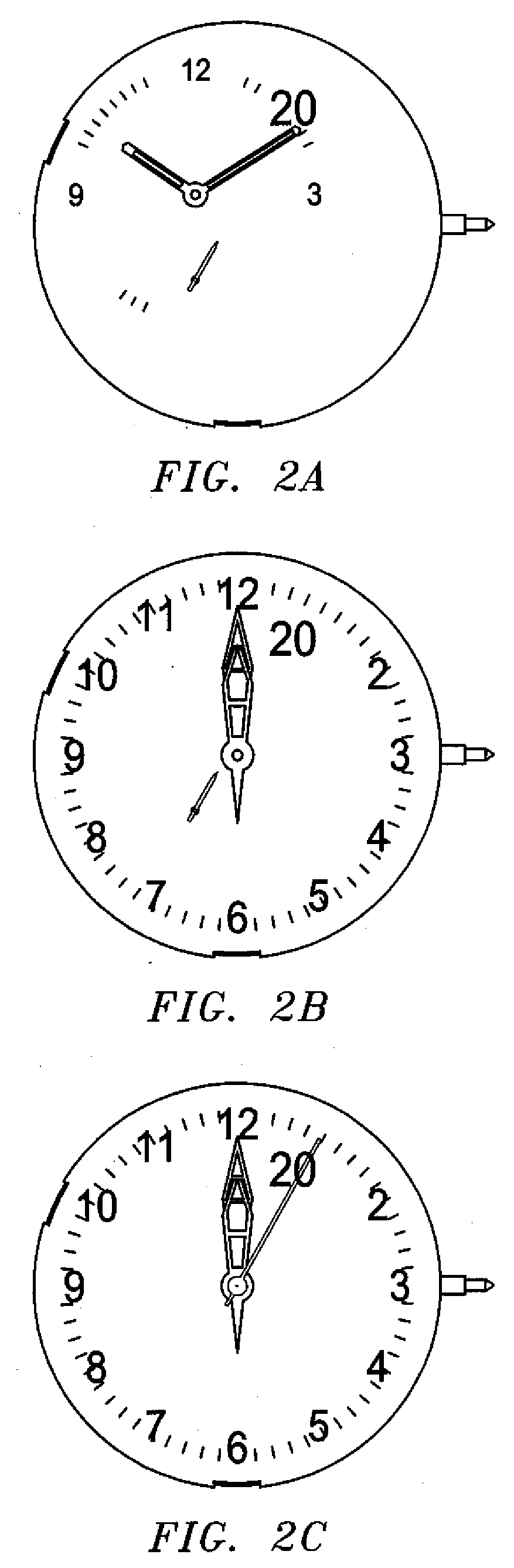
b. Full analog second time zone, such as:[0062]2-hand 12 or 24 hour indication of second zone[0063]complete “world time zone” compatibility with ¼ hr, ½ hour and ¾ hour capability[0064]interchangeable “home time” and “second time” in the primary time telling position

c. Full analog alarm time indication, with:[0065]2-hand 12 or 24 hour indication of alarm time second time zone alarm capability[0066]optional Alarm o...


PUM

PropertyMeasurementUnit
thickaaaaaaaaaa
thickaaaaaaaaaa
thickaaaaaaaaaa

Abstract

A wearable electronic device for conveying information using one or more display indicators, wherein the electronic device comprises a housing; a nest positioned in the housing; a plurality of independently insertable and removable modules coupled to the nest, wherein each module comprises (i) a gearing arrangement comprising at least one rotateable gear and (ii) a stepper motor, the stepper motor comprising a rotor rotateably coupled to the at least one rotateable gear; a controller operatively coupled to the stepper motor of each module, for causing the rotation of the rotor of each module; wherein each of the plurality of modules has associated therewith and mechanically coupled thereto one or more display indicators; whereby the positioning of the one or more indicators conveys information by referring to particular indicia. In a specific embodiment, the wearable electronic device is a wristwatch.

Description

BACKGROUND OF THE INVENTION[0001]This invention relates generally to wearable electronic devices, such as timepieces / wristwatches by example and not limitation, and in particular, to a wearable electronic device that incorporates a unique quartz analog movement construction and methodology therefor, which is microprocessor controlled, and which can accommodate multi-display indicator and multimotor movements.[0002]The industry of wearable electronic devices is filled with attempts to improve the construction, functionality, versatility and aesthetic appearance of such wearable electronic devices, all the while being mindful of and trying to reduce the associated manufacturing costs thereof In fact, it is believed that ongoing attempts try to accomplish one or more of the foregoing, even sometimes simultaneously, by balancing device characteristics and components to be used therein.[0003]It is well known that the prior art contains examples of watches that incorporate plastic movemen...

Claims


Application Information

Patent Timeline
02 Sep 2010
Publication
US20100220559A1
IPC
G04B19/02; G04D99/00
CPC
G04C3/008; Y10T29/49002; G04C17/00; G04C3/146
Inventors
GALIE, LOUIS M.; BURKHARDT, WOLFGANG