[0013]In the air spring device according to the present invention, the air spring, the shear spring means and the compression spring means are arranged in series alignment with each other. Such an arrangement ensures that, due to the virtue of series-connected springs, the function of the spring means having a lower spring constant becomes prevailing with reference to the application of a vertical load so that the load is primarily supported by the air spring and the shear spring means in a resilient and elastic manner. On the other hand, once the
abutment member begins to be operative in response to the increase in the vertical load beyond the deformation limit of the shear spring means, the load is primarily supported by the air spring and the compression spring means with relatively stiff spring constant. The same applies to a situation wherein the vertical load is elastically supported by both of the shear spring means and the compression spring means in a deflated state of the air spring due to puncture or the like, when the air spring is unable to perform its intended function.
[0014]When a horizontal load is applied to the air spring device, the load can be resiliently supported in elastic manner, primarily by a horizontal deformation of the air spring and the
shearing deformation of the compression spring means. Such an elastic support of the horizontal load is fully achieved whether or not the air spring is in a deflated state, by virtue of the series-connection of the shear spring means and the compression spring means, whereby the shearing spring constant of the compression spring means becomes prevailing regardless of the magnitude of the vertical load.
[0015]Thus, in the air spring device according to the present invention, even if a large vertical load is applied to such an extent that the shear spring means undergoes a deformation beyond its deformation limit and the subsequent elastic support of the vertical load is achieved solely by the function of the compression spring means, the horizontal load can be resiliently supported in elastic manner by the
shearing deformation of the compression spring means, whether or not the air spring is in a deflated state.
[0016]Incidentally, if the shear spring means and the compression spring means are successively arranged as seen from the side of the sir spring, and the lower face plate is provided with an
abutment member, which is brought into abutment with the compression spring means so as to
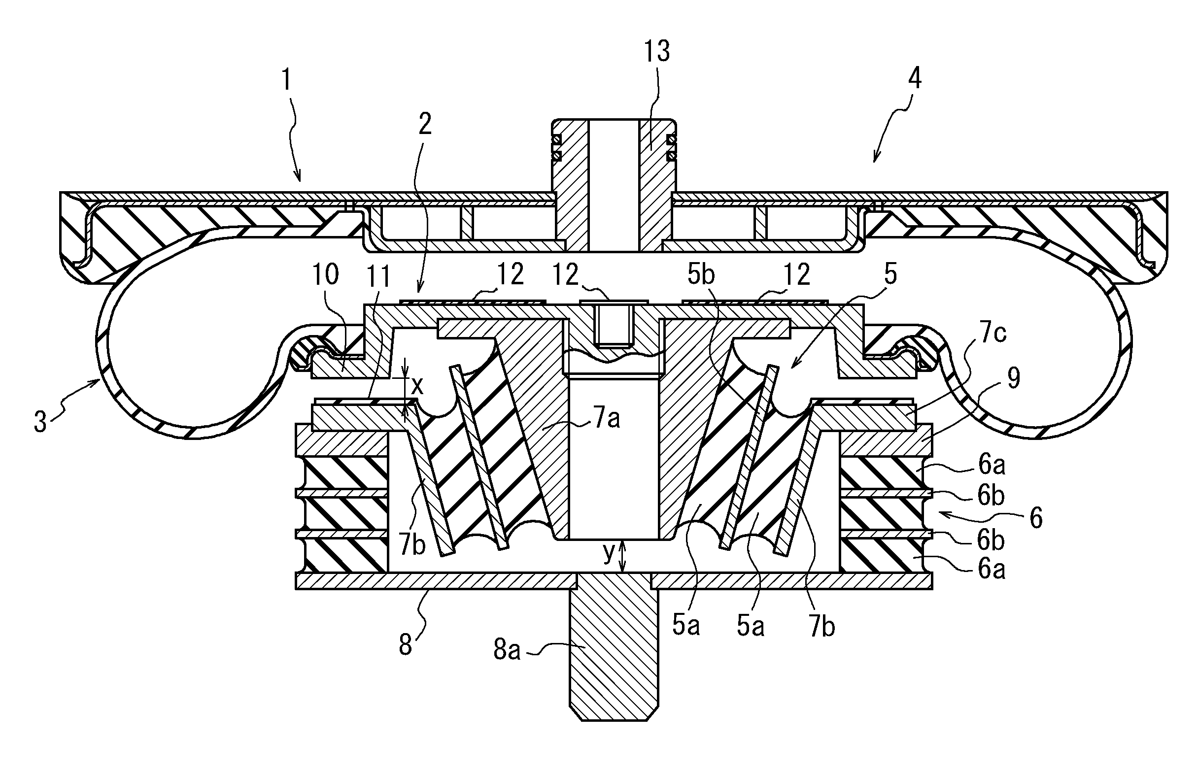
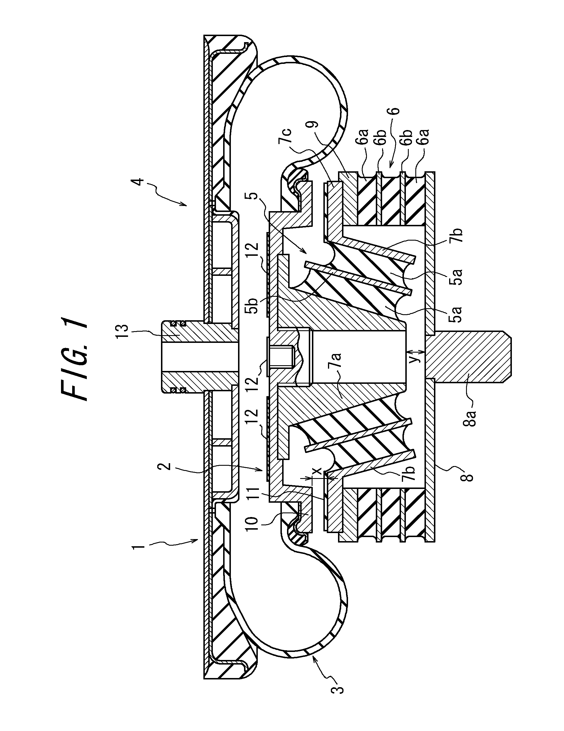
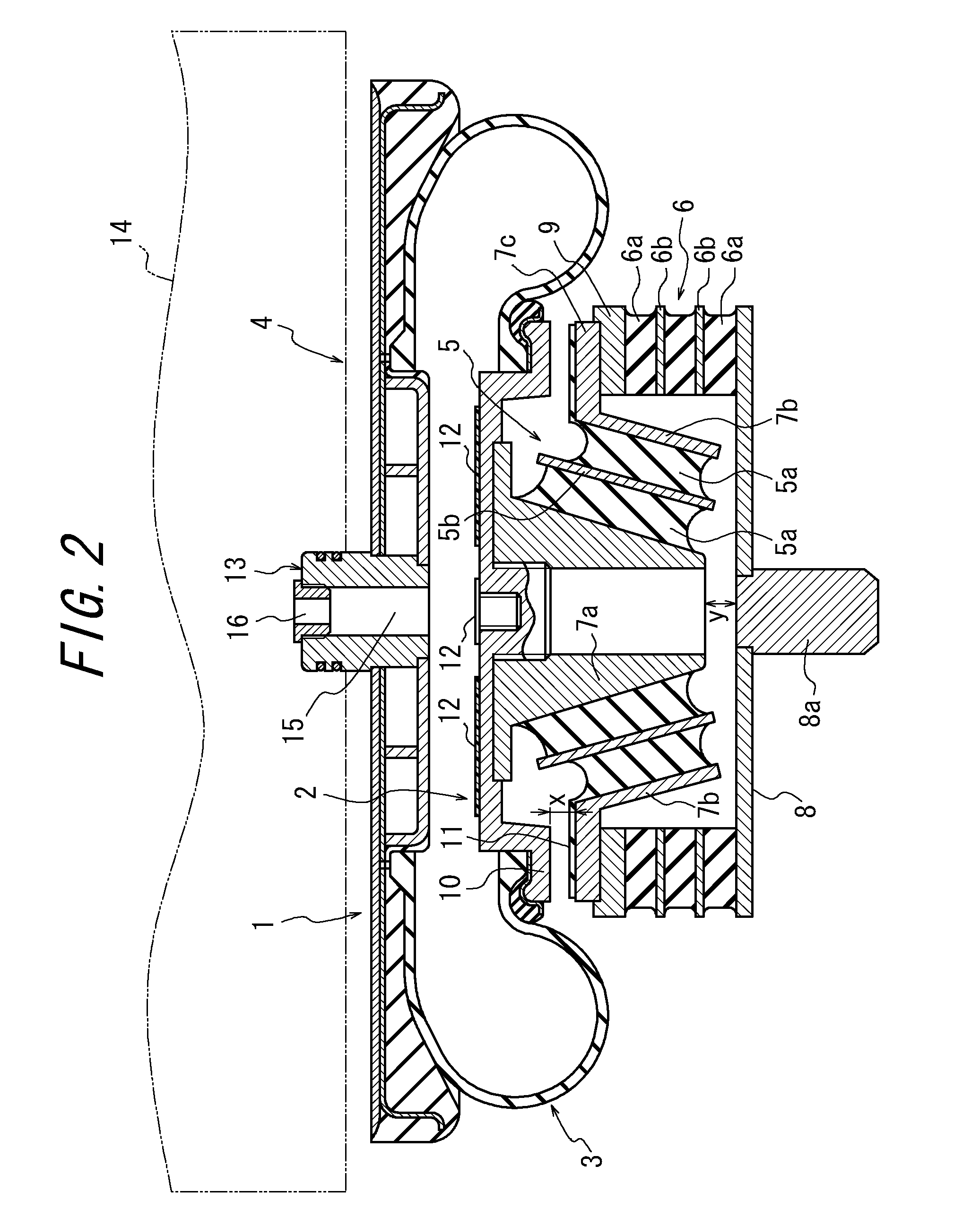
restrict the displacement amount of the shear spring means, and the abutment member is configured so as to leave a gap between the lower end support plate and the shear spring means after the abutment member has been brought into abutment with the side of the compression spring means, then it is possible to fully achieve the above-mentioned various functions with a simple structure of the spring device. It is further possible to cause the compression spring means to fully smoothly and positively function for elastically supporting the horizontal load, even when the shear spring means has been deformed to its limit position under the vertical load.
[0017]In the present invention, if the shear spring means comprises a laminated structure wherein the rubber members of frusto-conical shape and the rigid plates of frusto-conical shape are alternately laminated with each other, and the laminated structure is joined to the inner and outer cylinders, the rubber members are caused to deform not only in the shearing direction but also in the compression direction to provide a more or less incremental tendency of the spring constant. Thus, as compared to a case wherein only the shearing deformation is permitted, it is possible to suppress the absolute deformation amount of the rubber members, thereby providing improved durability of the rubber members. It is on the other hand possible for the shear spring means to contribute to the achievement of the elastic function in response to application of the horizontal load.
[0018]Also, if the compression spring means comprises a laminated structure wherein the rubber members of annular shape and the rigid plates of annular shape, both being horizontally arranged, for example, are alternately laminated with each other, and such laminated structure is joined to the lower end support member and the upper end ring, both being horizontally arranged, and the outer cylinder of the shear spring means has a
flange, which is fitted with the upper end ring, it is possible for the compression spring means to exhibit a relatively stiff spring constant upon application of the vertical load, and a relatively resilient spring constant under the shearing deformation of the annular rubber members upon application of the horizontal load.

