Apparatus and method for preventing particle interference of downhole devices

a technology of particle interference and equipment, applied in the direction of fluid removal, wellbore/well accessories, construction, etc., can solve the problems of often stopping esp's, intentional and unintentional, and sand management in the well bore, so as to prevent particle interference with lifting equipment, improve safety, and improve safety. the effect of operation efficiency

Active Publication Date: 2018-09-25
FORUM US
View PDF28 Cites 10 Cited by
  • Summary
  • Abstract
  • Description
  • Claims
  • Application Information

AI Technical Summary

Benefits of technology

[0007]Problems with ESP operation are addressed by the device and methods of the present invention which tend to prevent particle accumulation on the ESP when not in use and provide for more efficient operation. Therefore the reliability, efficiency, timeliness and the likelihood of a successful restart of an ESP is greatly increased. Generally, the device prevents particle interference with lifting equipment, such as an ESP, in a well bore having a production tubing string using a tube positioned between the lifting equipment and the surface and in fluid communication with the lifting equipment and the production tubing string. An annulus portion is defined around the tube, e.g. with a cylinder spaced from and surrounding the tube. The device includes a check valve proximate at least one end of the tube which operates to permit fluid flow from the lifting equipment to the surface, but prevents fluid flow from the tube to the lifting equipment. The device has a plurality of ports positioned in the wall of the tube which operate to permit fluid flow from the tube into the annulus during operation of the lifting equipment and operable to inhibit particles from entering the tube when the lifting equipment is not operating. Preferably, the ports are angled in the direction of the lifting equipment and can be more dense closest to the lifting equipment.
[0008]One method of the present invention operates to inhibit particle impediment to lifting equipment, such as an ESP, when not in use. Generally, the lifting equipment is positioned in the well bore downhole from the surface and operable to pump fluid through a production tubing string to the surface. A particle-excluding device is connected to the production tubing string between the lifting equipment and the surface, the device having a central tubular portion, a surrounding annulus portion, a plurality of spaced ports communicating between the tube and the annulus and a check valve between the ports and the lifting equipment. The lifting equipment is operated so that fluid flows through the check valve, ports, tubular portion and at least some of the annulus portion and into the production tubing. The method inhibits particles in the fluid from accumulating on the lifting equipment when the lifting equipment is not in use by trapping a substantial portion of particles in the annulus, whereby the ports inhibit particle flow into the tubing portion. The check valve prevents reverse fluid flow to the lifting equipment when not in use, and thus prevents the ESP from spinning backwards due to a reversal of the fluid flow.

Problems solved by technology

Management of sand in the well bore has long been an issue.
However, ESP's are often stopped, both intentionally and unintentionally.
For example, electric reliability and power fluctuations often stop ESP operation or the ESP is stopped for maintenance or production issues.
The sand settles on the ESP which not only induces component failures in the ESP, but also makes restart of the ESP difficult because the ESP must first clear substantial amounts of sand from the production tubing.
Failure and replacement of an ESP is not only expensive because of the rework required in the well, but also because of the lost production time.Several attempts have been made to prevent sand accumulation on ESP's particularly when the ESP is idle.
However, each of these existing tool designs has limitations which lead to suboptimal performance, and many are unnecessarily complex and expensive.

Method used


Image

  • Apparatus and method for preventing particle interference of downhole devices
  • Apparatus and method for preventing particle interference of downhole devices
  • Apparatus and method for preventing particle interference of downhole devices

Examples


first embodiment

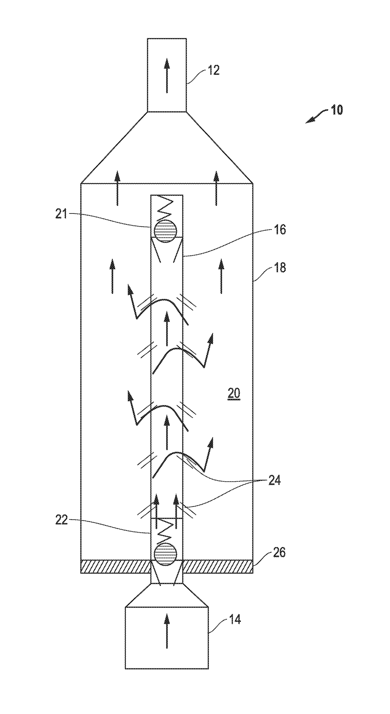
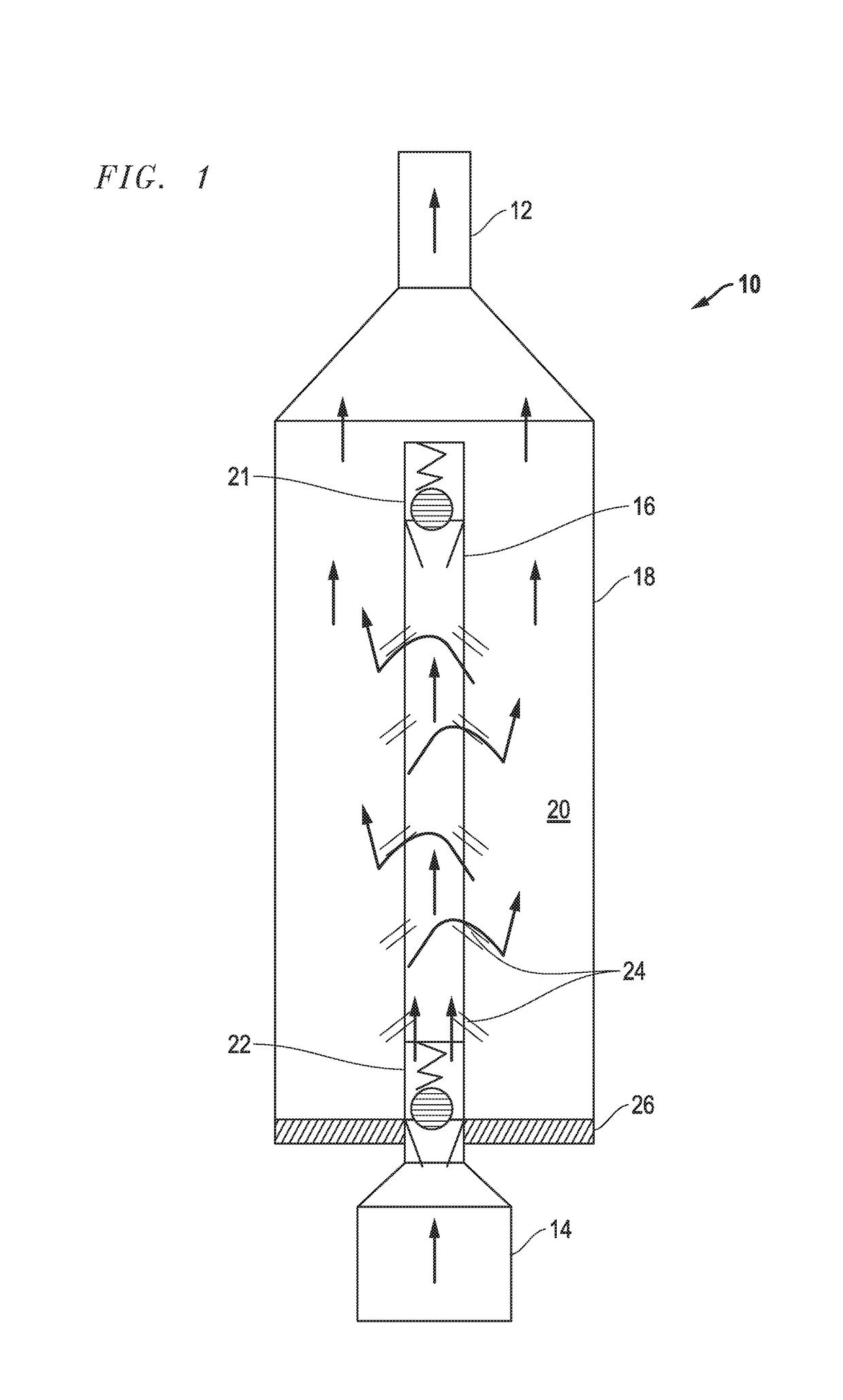
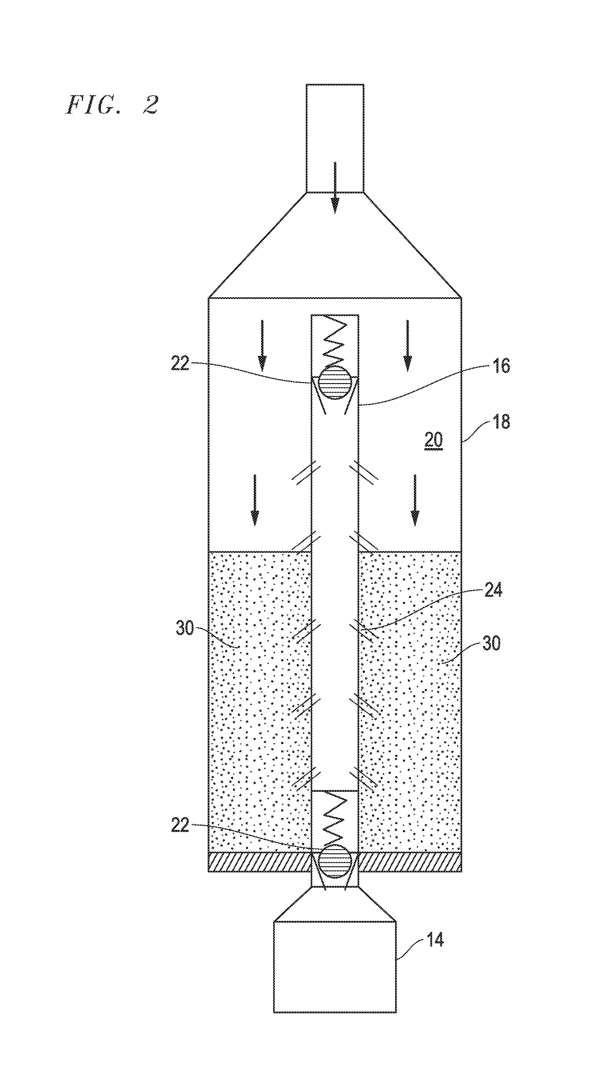
[0020]Turning to the drawings, a device 10 in accordance with the present invention is illustrated in FIGS. 1-5. The device 10 is inserted as part of the production tubing string with FIG. 1 showing production tubing 12 leading to the surface and ESP 14 located downhole adjacent to the device 10. It should be understood that the device 10 can be spaced from the ESP and in fact, multiple devices 10 can be used in the production tubing string. Further, while FIG. 1 appears as a conventional vertical orientation, the device 10 can also be used in horizontal wells. Additionally, while the usefulness of the device 10 is illustrated in this embodiment as protecting an ESP, other downhole devices can be similarly protected from particles such as sand or fracking proppants.

[0021]Generally, the device 10 includes a central production tube 16 surrounded by an enlarged cylinder housing 18. Thus, the area between the tube 16 and the inner walls of the cylinder 18 define an annulus 20. At each e...

second embodiment

[0029]a device 50 in accordance with the present invention is illustrated in FIGS. 6-9. The device 50 is inserted as part of the production tubing string with FIG. 6 showing production tubing 12 leading to the surface and ESP 14 located downhole adjacent to the device 50. It should be understood that the device 50 can be spaced from the ESP and in fact, multiple devices 50 can be used in the production tubing string. Further, while FIG. 6 appears as a conventional vertical orientation, the device 50 can also be used in horizontal wells. Additionally, while the usefulness of the device 50 is illustrated in this embodiment as protecting ESP 14, other downhole devices can be similarly protected from particles such as sand or fracking proppants.

[0030]Generally, the device 50 includes a central cylindrical tube 56 surrounded by an enlarged cylinder housing 58. Thus, the area between the tube 56 and the inner walls of the cylinder 18 define an annulus 60. At the distal end 72 of the tube ...


PUM


Abstract

A device and method for inhibiting particle (e.g., sand) accumulation on down hole equipment, such as an ESP, particularly when the equipment is not in use. The device and methods permit the equipment to start and stop with fewer break downs and at greater efficiency. The device includes a central tubular section connecting the equipment to the production tubing string. The tubular section is surrounded by an annulus and a number of ports in the tubular section angled to allow fluid communication between the tubular section and the annulus during operation, but prevent particles from flowing from the annulus into the tubular section when not in use. A check valve between the tube and ESP assists in isolating the ESP from sand.

Description

PRIORITY CLAIM[0001]The present application claims priority to U.S. Provisional Application No. 62 / 334,174 filed May 10, 2016, which is incorporated by reference herein.BACKGROUND OF THE INVENTION1. Field of the Invention[0002]This invention relates to systems and methods to prevent particle interference with downhole equipment, such as an electrical submersible pump (ESP).2. Description of the Relevant Art[0003]Management of sand in the well bore has long been an issue. Many oil and gas wells are in sand-producing intervals, such as sandstones. There are several forms of artificial lift of the production fluids, with the most common being the electrical submersible pump (ESP). In recent years, unconventional wells have gained wide spread acceptance and often involve horizontal production tubing, ESP's for lift, and multiple, highly fractured production intervals, often in shale or other unconsolidated formations.[0004]In such highly fractured, horizontal wells, the use of proppants...

Claims


Application Information

Patent Timeline
Patent Type & Authority Patents(United States)
IPC IPC(8): E21B43/38E21B34/08E21B43/12E21B27/00E21B34/00
CPCE21B43/38E21B27/00E21B43/128E21B34/08E21B2034/002E21B2200/04E21B43/35
Inventor FIELDER, III, ROBERT P.MEIER, KYLESHELINE, EVAN
Owner FORUM US
Why Eureka
Try Eureka