Illumination apparatus and sensor unit

a technology of illumination apparatus and sensor unit, which is applied in the direction of mechanical apparatus, lighting and heating apparatus, instruments, etc., can solve the problems of excessive light from a light source and reduced light emitted from the light source side, so as to prevent a reduction in the amount of light emitted

Active Publication Date: 2018-10-02
CANON COMPONENTS INC
View PDF8 Cites 0 Cited by
  • Summary
  • Abstract
  • Description
  • Claims
  • Application Information

AI Technical Summary

Benefits of technology

[0007]However, the sectional shape of the light guide of Patent Document 1 is the same at any position in the longitudinal direction. Therefore, the light from a light source tends to be excessively guided in the longitudinal direction, and the amount of light emitted from the light source side is reduced.
[0008]In the light guide of Patent Document 2, the diffusion means is provided only on the light reflection portion, and the amount of light emitted from the light source side is reduced.
[0009]In the light guide of Patent Document 3, the pattern surface is not formed on the incident surface side, and the amount of light emitted from the light source side is reduced.
[0013]The present invention has been made in view of the problems, and an object of the present invention is to prevent a reduction in the amount of light emitted from a light source side in the light emitted from a light guide.

Problems solved by technology

Therefore, the light from a light source tends to be excessively guided in the longitudinal direction, and the amount of light emitted from the light source side is reduced.

Method used


Image

  • Illumination apparatus and sensor unit
  • Illumination apparatus and sensor unit
  • Illumination apparatus and sensor unit

Examples


first embodiment

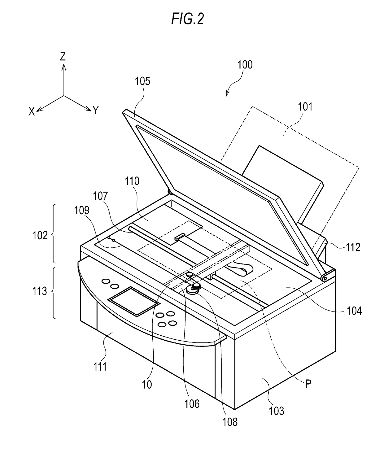
[0030]A structure of a multi-function printer (MFP) as an example of the image reading apparatus or the image forming apparatus according to the present embodiment will be described with reference to FIG. 2. FIG. 2 is a perspective view illustrating an appearance of an MFP 100. As illustrated in FIG. 2, the MFP 100 includes: an image reading portion 102 as image reading means for reading reflected light from the original P; and an image forming portion 113 as image forming means for forming (printing) an image of the original P on a sheet 101 (recording paper) as a recording medium.

[0031]The image reading portion 102 has a function of a so-called image scanner and is configured, tor example, as follows. The image reading portion 102 includes: a housing 103; a platen glass 104 as an original placing portion made of a glass transparent plate; and a platen cover 105 that can be freely opened and closed relative to the housing 103 so as to be able to cover the original P.

[0032]The housi...

second embodiment

[0084]A positioning portion 90 is formed on the light guide 20 in the case described in the present embodiment. The same reference signs are provided to the same components as in the first embodiment, and the description of the same components will not be repeated.

[0085]FIGS. 9A and 9B are diagrams illustrating a configuration of the light guide 20 of a second embodiment.

[0086]The positioning portion 90 is integrally molded on the position of the light guide 20 where the incident surface 21 is provided in the first embodiment. In the present embodiment, an end surface of the positioning portion 90 is an incident surface 91 that receives the light from the light source 40. The positioning portion 90 is rectangular as viewed in the longitudinal direction of the light guide 20 and functions as a flange portion larger than the sectional shape of the light guide 20. More specifically, the positioning portion 90 of the light guide 20 can be fitted into a predetermined position of the fram...

third embodiment

[0089]Next, a configuration in which the image sensor unit 10 is applied to a flat-bed type scanner 130 as an image reading apparatus will be described with reference to FIG. 10.

[0090]FIG. 10 is a perspective view illustrating an example of the configuration of the flat-bed type scanner 130.

[0091]The scanner 130 includes a housing 131, a platen glass 132 as an illuminated object placing portion, the image sensor unit 10, a driving mechanism that drives the image sensor unit 10, a circuit board 133, and a platen cover 134. The platen glass 132 is made of a transparent plate, such as glass, and is attached to the upper surface of the housing 131. The platen cover 134 is attached to the housing 131 through a hinge mechanism or the like so as to cover the original P placed on the platen glass 132, and the platen cover 134 can be opened and closed. The image sensor unit 10, the driving mechanism that drives the image sensor unit 10, and the circuit board 133 are housed in the housing 131...


PUM


Abstract

Provided is an illumination apparatus that applies light to an original, the illumination apparatus including: a light source; and a rod-shaped light guide including: an incident surface that receives the light from the light source; a reflection surface provided with a diffusion portion that diffuses the light incident on the incident surface; and an emission surface that emits, to the original, the light diffused by the diffusion portion. An area of the light guide is reduced by an inclination of the light guide from the incident surface side to a middle part in a longitudinal direction of the light guide, and the light guide is provided with the diffusion portion from the incident surface side to the middle part on the reflection surface.

Description

CROSS-REFERENCE TO RELATED APPLICATIONS[0001]This application is based upon and claims the benefit of priority of the prior Japanese Patent Application No. 2016-078209, filed on Apr. 8, 2016, and the Japanese Patent Application No. 2017-076137, filed on Apr. 6, 2017, the entire contents of which are incorporated herein by reference.BACKGROUND OF THE INVENTIONField of the Invention[0002]The present invention relates to an illumination apparatus and a sensor unit.Description of the Related Art[0003]An illumination apparatus that linearly illuminates an illuminated object is known.[0004]An illumination apparatus disclosed in Patent Document 1 includes a light guide that emits, from a light emission surface, illumination light incident on an end surface. The light guide of Patent Document 1 has a linear shape, and recessed spherical surfaces are formed on a bottom surface.[0005]A light guide disclosed in Patent Document 2 has a structure with a combination of a pyramid portion and a fla...

Claims


Application Information

Patent Timeline
Patent Type & Authority Patents(United States)
IPC IPC(8): H04N1/04H04N1/028F21V8/00F21V5/04G02B6/00
CPCH04N1/02855F21V5/04G02B6/0001H04N1/02895H04N2201/0094G02B2006/0098H04N2201/0081
Inventor YOSHIDA, HIDEMASATSUMEKAWA, YOSHIHIKOTAKESHITA, AKIHITO
Owner CANON COMPONENTS INC
Why Eureka
Try Eureka