Optical sensor

a technology of optical sensors and sensors, applied in the field of optical sensors, can solve the problems of high energy consumption of power-hungry light sources, high cost of heat sinks, and inaccurate measurement of drive currents, and achieve the effect of accurate measurement, accurate measurement of media items, and accurate measuremen

Active Publication Date: 2010-06-24
NCR CORP
View PDF3 Cites 0 Cited by
  • Summary
  • Abstract
  • Description
  • Claims
  • Application Information

AI Technical Summary

Benefits of technology

[0011]By pulsing the light source, rather than using continuous illumination, thermal problems associated with the light source can be avoided or at least reduced.
[0021]To achieve the desired drive current shown in column four of Table 1 above, in one embodiment, the amount of light to be detected by the optical receiver is reduced as the amount of light emitted by the light source is increased. One convenient way of implementing this is to use a differential amplifier coupled to the light source input and the comparator, so that an increasing input voltage at the light source is converted into a falling detected light threshold for the optical receiver. This has the effect that as more light is generated by the light source (indicating that multiple media items may be present), less light is required at the optical receiver to meet the detected light threshold. By selecting appropriate values of resistors for the differential amplifier, a linear relationship between media items and current can be achieved.
[0022]The variable current drive may further comprise a variable clock so that a slow clock rate is used when the counter value is low, and increases as the counter value increases. This reduces the effect of latency within the optical receiver because the light source emission is only increased relatively slowly at low counts. Low cost optical receivers typically have a latency of two to three microseconds when operating at the lowest 10% of their optical detection characteristics. This means that the optical receiver may not detect the threshold being reached until several microseconds after the threshold should have been reached. This has the effect of a null value (value of the counter when no media item is present) being too high.
[0026]By using an optical sensor, media items having transparent tape can be accurately counted; by using a non-optical sensor, media items having dirt thereon can be accurately counted; by using both an optical and a non-optical sensor, a more accurate determination of media items can be made, even if they are contaminated with dirt or transparent tape.

Problems solved by technology

One disadvantage of this arrangement is that a powerful light source (LED) is required that has a high energy consumption and requires expensive heat sinks.
This means that the value of the drive current is not an accurate measure for ascertaining the number of banknotes present.
This type of NTS is accordingly relatively expensive.

Method used


Image

  • Optical sensor
  • Optical sensor
  • Optical sensor

Examples


Embodiment Construction

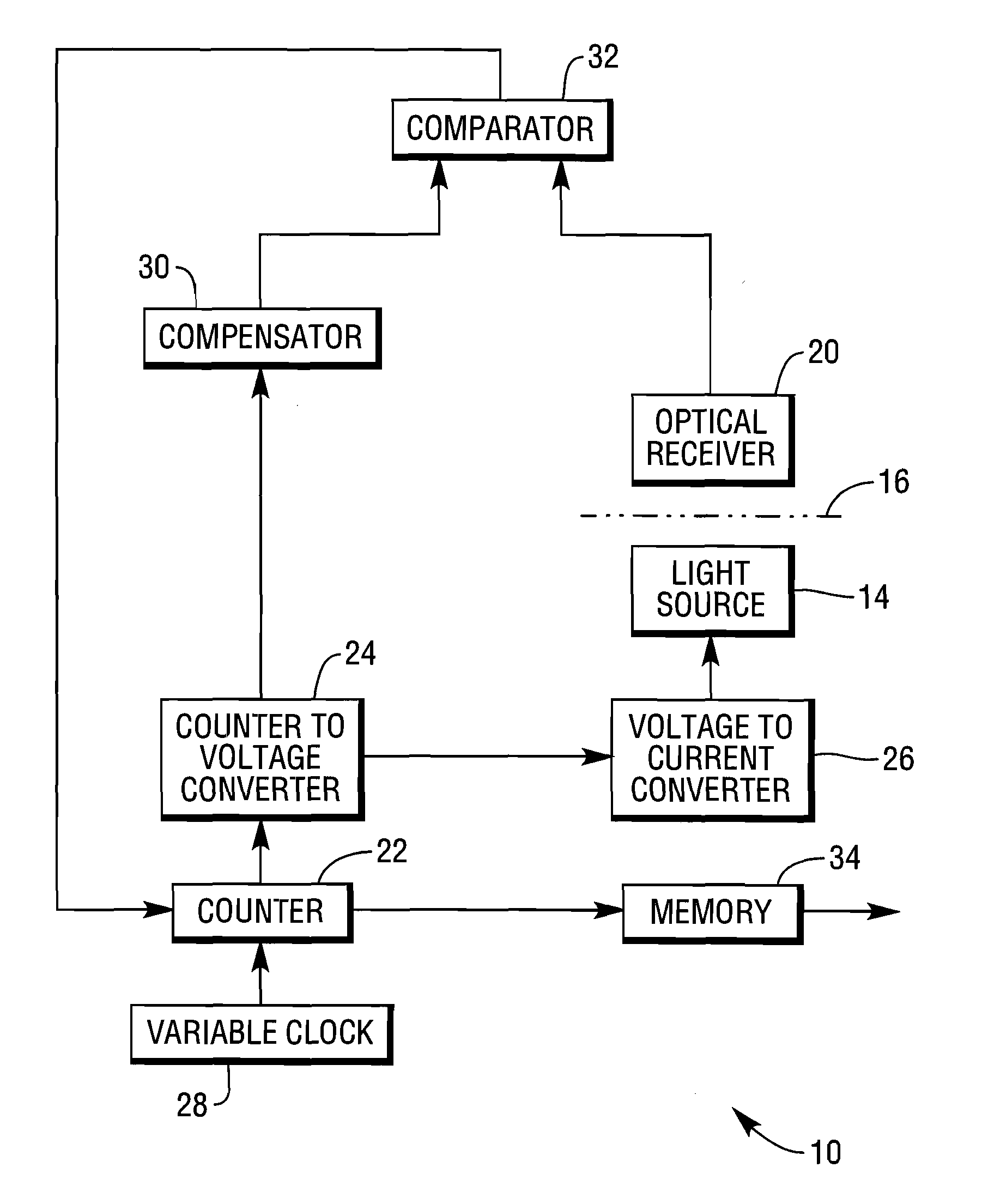
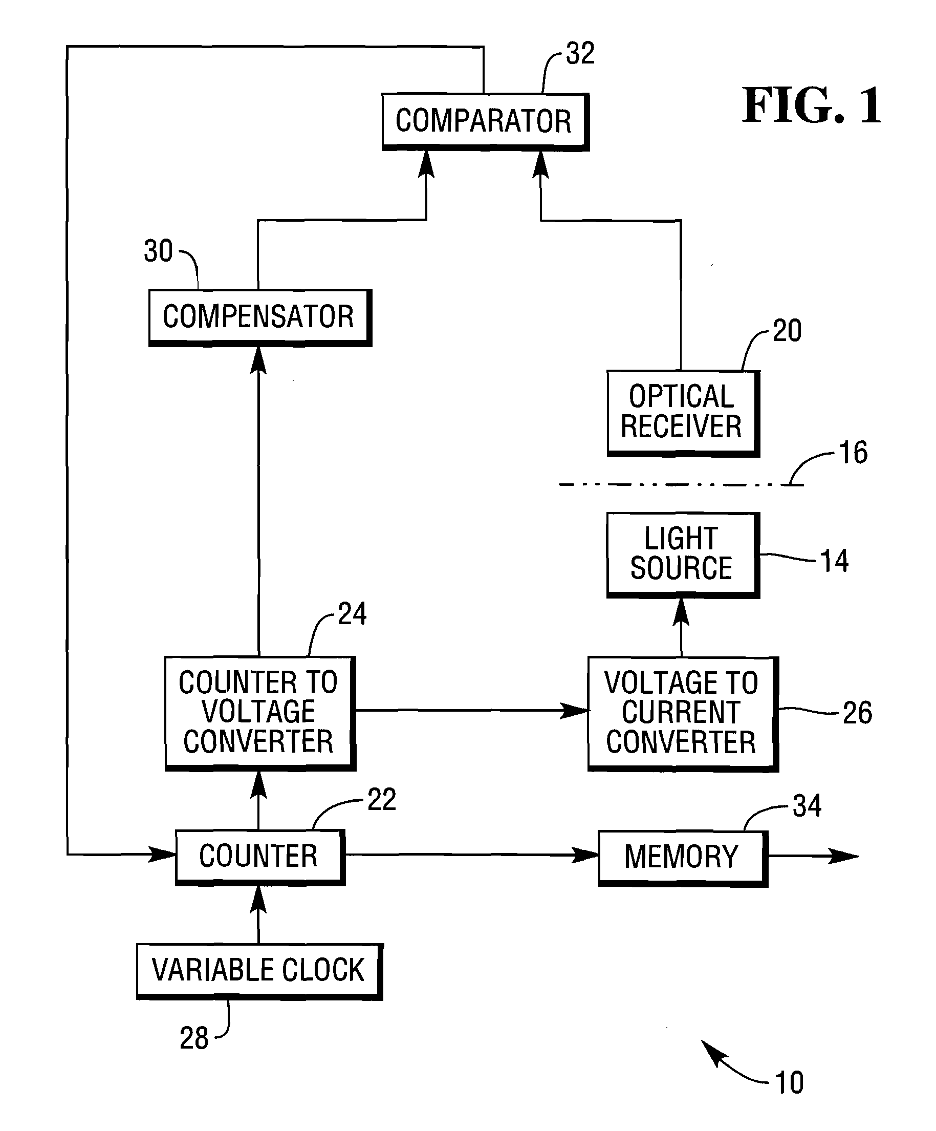
[0035]Reference is first made to FIG. 1, which is a block diagram of an optical sensor 10 according to one embodiment of the present invention.

[0036]The optical sensor 10 has a light source 14 in the form of a low cost infra-red (IR) light emitting diode (LED). The IR LED 14 is located on one side of a transport path (indicated by chain line 16). On an opposite side of the transport path 16 is an optical receiver 20 in the form of a photodiode. The photodiode 20 is aligned with the IR LED 14 to detect emission therefrom. A digital counter 22 is coupled to a counter to voltage converter 24, which is coupled to a voltage to current converter 26, which in turn drives the IR LED 14.

[0037]The digital counter 22 is regulated by a variable clock 28, having a low frequency (for example, 1 MHz) at relatively low counts of the counter 22 and a high frequency (for example, 32 MHz) at relatively high counts of the counter 22. The counter to voltage converter 24 is also coupled to a compensator ...


PUM


Abstract

An optical sensor comprises: a light source located on one side of a transport path; a variable current drive, an optical receiver in communication with the variable current drive, and located on an opposite side of the transport path to the light source and aligned therewith to detect light output therefrom; and a memory coupled to the variable current drive. The variable current drive is suitable for energising the light source so that the light intensity from the light source increases with increasing current. The variable current drive includes (i) a drive circuit for applying a pulse of current to the light source, during which pulse the light source is energised; and (ii) a counter for increasing the amount of current applied by the drive circuit during a pulse of current. The memory may be arranged to store a value from the counter indicative of a number of media items present in the transport path.

Description

FIELD OF INVENTION [0001]The present invention relates to an optical sensor and a method of sensing media using an optical sensor.BACKGROUND OF INVENTION [0002]Optical sensors are commonly used for a variety of functions including detecting skewed or multiple picked media items within a media handler in a self-service terminal. One type of self-service terminal that relies on an accurate optical sensor is an Automated Teller Machine (ATM). An ATM typically includes a cash dispenser having a pick unit for picking individual banknotes and conveying these banknotes to a banknote transport mechanism for delivery to an ATM customer.[0003]ATMs have used a variety of different optical and non-optical detectors to detect banknote skew and multiple picked banknotes. These sensors are sometimes referred to as note thickness sensors (NTS). One particular type of NTS relies on compensated opacity, and is described in U.S. Pat. No. 7,049,572.[0004]The design of the NTS in U.S. Pat. No. 7,049,572...

Claims


Application Information

Patent Timeline
Patent Type & Authority Applications(United States)
IPC IPC(8): G01J1/32
CPCB65H7/12B65H2511/524G07D7/166G07D7/121B65H2701/1912B65H2557/23B65H2553/412B65H2515/704B65H2515/60B65H2220/02B65H2220/01B65H2220/03G07D7/183B65H2515/70
Inventor MILNE, DOUGLAS L.
Owner NCR CORP
Why Eureka
Try Eureka