Illuminating device and method of calibrating illuminating device

a technology of illuminating device and illumination device, which is applied in the direction of television system, process and machine control, instruments, etc., can solve the problems of inability to detect the edges of the workpiece, inability to obtain the image of the workpiece, so as to reduce the calibration cost of the user, shorten the calibration time of the illuminating device, and reduce the cost of calibration

Active Publication Date: 2011-03-03
MITUTOYO CORP
View PDF2 Cites 5 Cited by
  • Summary
  • Abstract
  • Description
  • Claims
  • Application Information

AI Technical Summary

Benefits of technology

[0018]In this aspect of the invention as well, in the same way as described above, it is sufficient to conduct the time-consuming illuminance measurement only once at the time of calibrating the conversion table, the calibration o

Problems solved by technology

In the image processing apparatus, if the illuminance becomes lower than the commanded illuminance, the quantity of light becomes insufficient, in which case there are possibilities that an image of the workpiece cannot be obtained, and edges of the workpiece cannot be detected.
Meanwhile, if the illuminance becomes higher than the commanded illuminance, the image of the workpiece becomes blurred, possibly making it impossible to detect edges of the workpiece.
For these reasons, with the illuminating device used in the image processing apparatus, controlling of the light source such that the commanded illuminance can be obtained becomes an extremely important issue.
However, since the LED undergoes a decline in illuminance with the lapse of time, with the illuminating device of JP-A-2004-220834, after

Method used


Image

  • Illuminating device and method of calibrating illuminating device
  • Illuminating device and method of calibrating illuminating device
  • Illuminating device and method of calibrating illuminating device

Examples


Embodiment Construction

[0029]Hereafter, a description will be given of an embodiment of the invention with reference to the accompanying drawings.

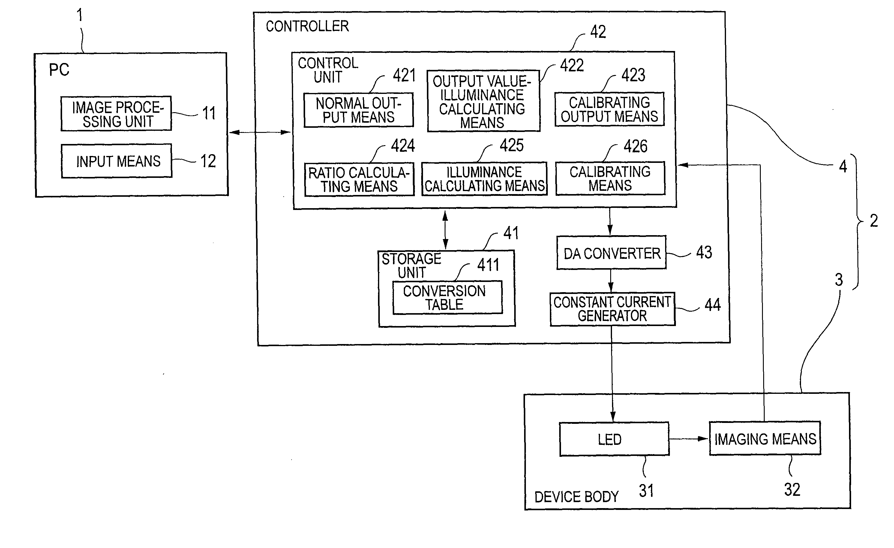
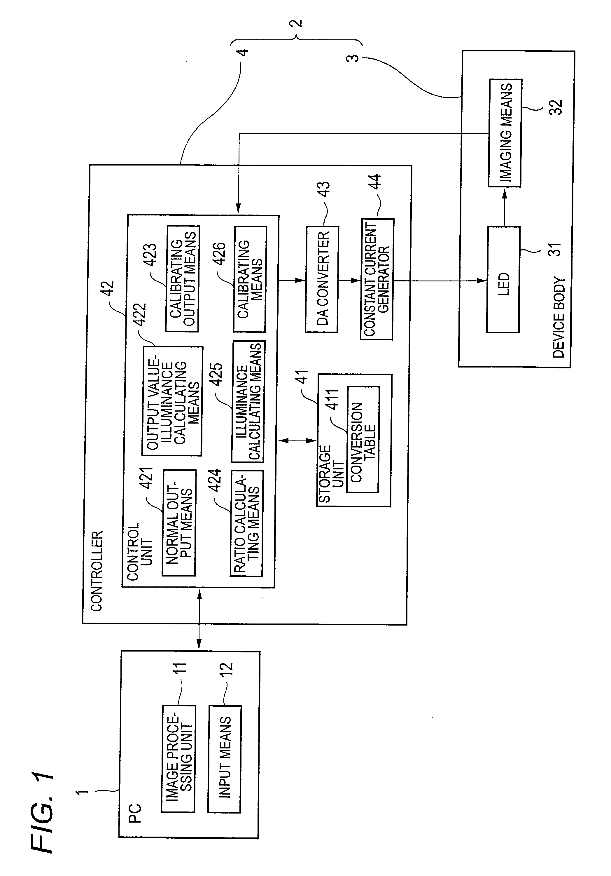
[0030]FIG. 1 is a block diagram illustrating the configuration of an image processing apparatus in accordance with this embodiment. The image processing apparatus is comprised of a personal computer (PC) 1 and an illuminating device 2. The PC 1 has an image processing unit 11 and an input unit 12. The image processing unit 11 performs such as the edge detection of a workpiece on the basis of a picked-up image of the workpiece imaged by the illuminating device 2 and calculates the profile of the workpiece. The input unit 12 is configured by manually operable buttons or the like, and inputs to the illuminating device 2 a brightness command value, i.e., a command value with respect to the illuminance of the illuminating light to be applied to the workpiece by the illuminating device 2, within a range of 0 to 100%.

[0031]The illuminating device 2 has a device body 3 ...


PUM


Abstract

An illuminating device includes: a calibrating output unit for reading an output current command value corresponding to a specific brightness command value and for outputting the output current command value to a light source; a ratio calculating unit for calculating a ratio between an illuminance of illuminating light emitted from the light source and a prescribed illuminance value prescribed for the specific brightness command value; an illuminance calculating unit for calculating each illuminance when each output current command value matched with each brightness command value is outputted; and a calibrating unit for calibrating a relationship between each brightness command value and each output current command value in a conversion table such that each illuminance at the time when each output current command value matched with each brightness command value is outputted is set to each prescribed illuminance value prescribed for each of the brightness command values.

Description

CROSS-REFERENCE TO RELATED APPLICATION(S)[0001]This application is based upon and claims the benefit of priority from Japanese Patent Application No. 2009-199439, filed on Aug. 31, 2009, the entire contents of which are incorporated herein by reference.BACKGROUND[0002]1. Field of the Invention[0003]The present invention relates to an illuminating device and a method of calibrating an illuminating device.[0004]2. Description of the Related Art[0005]Conventionally, an image processing apparatus is used which is provided with an illuminating device having an LED (light emitting diode) for irradiating a workpiece with light and a controller for controlling the LED, and in which an image of the workpiece is obtained by irradiating the workpiece with light by the illuminating device so as to determine a profile of the workpiece from the image of the workpiece. The controller reads from a predetermined conversion table an output current command value corresponding to a brightness command v...

Claims


Application Information

Patent Timeline
IPC IPC(8): H05B37/02
CPCH04N17/002H04N5/2354H04N23/74
Inventor YOSHIDA, HIROYUKISHIRAI, NAOKI
Owner MITUTOYO CORP
Why Eureka
Try Eureka