
Control device, radiography system, control method, and control program

Inactive Publication Date: 2022-08-25
FUJIFILM CORP
View PDF0 Cites 0 Cited by
  • Summary
  • Abstract
  • Description
  • Claims
  • Application Information

AI Technical Summary

Benefits of technology

The patent aims to provide a control device, a radiography system, a control method, and a control program that can decrease the time it takes to calibrate the voltage supplied to a radiation tube's gate electrode.

Problems solved by technology

In the related art, since calibration is performed in a state in which the operation of the radiography system is stopped, for example, at night, there is a problem that it is difficult to shorten the calibration interval.

Method used


Image

  • Control device, radiography system, control method, and control program
  • Control device, radiography system, control method, and control program
  • Control device, radiography system, control method, and control program

Examples


Embodiment Construction

[0031]Hereinafter, an embodiment of the present disclosure will be described in detail with reference to the drawings. In addition, this embodiment does not limit the present disclosure.

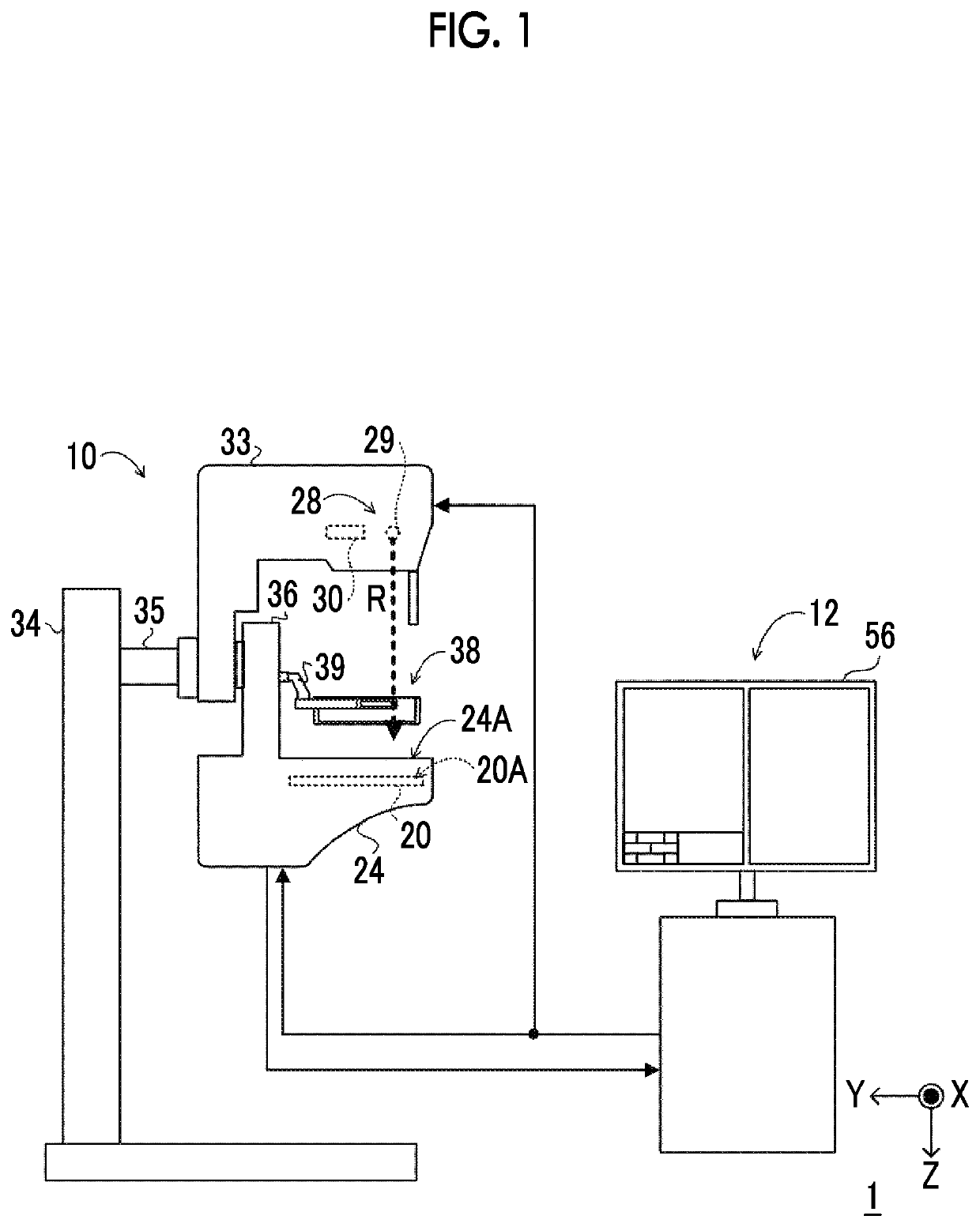
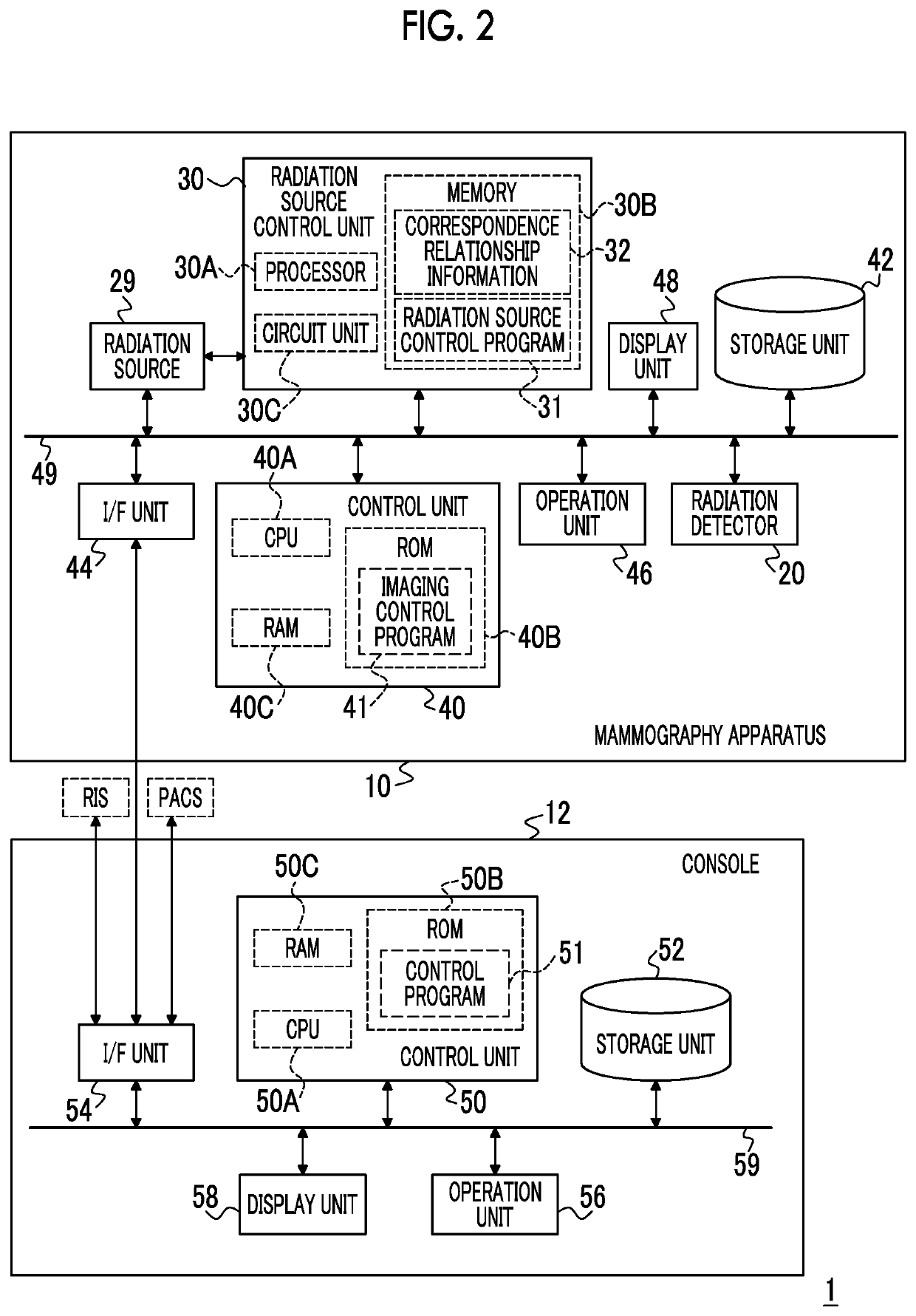
[0032]First, an example of the overall configuration of a radiography system according to this embodiment will be described. FIG. 1 is a diagram illustrating an example of the overall configuration of a radiography system 1 according to this embodiment. As illustrated in FIG. 1, the radiography system 1 according to this embodiment comprises a mammography apparatus 10 and a console 12.

[0033]First, the console 12 according to this embodiment will be described. The console 12 according to this embodiment has a function of controlling the mammography apparatus 10 using, for example, an imaging order and various kinds of information acquired from a radiology information system (RIS) through a wireless communication local area network (LAN) or the like and instructions input by a user, such as a doctor or...


PUM


Abstract

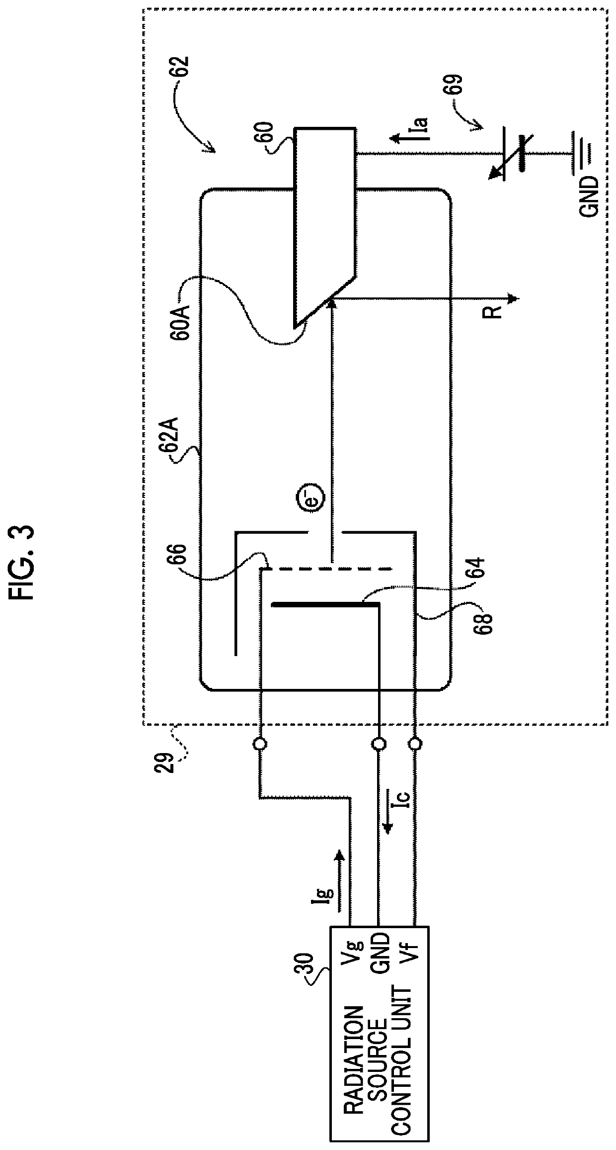
Within one imaging period, a processor of a control device supplies a gate voltage, performs control to correct a voltage value of the gate voltage on the basis of a difference between a current value of an estimated anode current, which flows from a power supply voltage generator to an anode unit and is estimated on the basis of a detection value of a cathode current flowing from a cathode unit to a ground and a detection value of a gate current flowing from the power supply voltage generator to a gate electrode, and a target current value of an anode current set for an n-th imaging operation, and performs control to set the voltage value of the gate voltage corresponding to a corrected voltage value of the gate voltage corrected at the end of the n-th imaging operation and a target current value of the anode current set for an (n+1)-th imaging operation as a voltage value of the gate voltage which is supplied to the gate electrode first in the (n+1)-th imaging operation.

Description

CROSS-REFERENCE TO RELATED APPLICATIONS[0001]The present application claims priority under 35 U.S.C. § 119 to Japanese Patent Application No. 2021-025437 filed on Feb. 19, 2021. The above application is hereby expressly incorporated by reference, in its entirety, into the present application.BACKGROUND1. Technical Field[0002]The present disclosure relates to a control device, a radiography system, a control method, and a control program.2. Description of the Related Art[0003]A radiography system that captures a radiographic image of an object is known. The radiography system has a radiation tube that generates radiation. As the radiation tube, in addition to a radiation tube that heats a filament as an electrode to emit thermal electrons, a radiation tube comprising a cold cathode that emits electrons without heating the electrode is known. The radiation tube comprises an electron emitting unit constituting a cold cathode and an anode unit (see, for example, WO2019 / 151251A). The ele...

Claims


Application Information

Patent Timeline
IPC IPC(8): A61B6/00G06T7/00
CPCA61B6/502G06T7/0012G06T2207/30068H05G1/34H05G1/085
Inventor SATO, MASARU
Owner FUJIFILM CORP
Learn More