Calibration method and calibration tool of camera

a technology of calibration tool and camera, which is applied in the field of plurality of cameras, can solve the problems of complicated calibration work, insufficient consideration of the case of calibrating the plurality of cameras,

Active Publication Date: 2019-11-26
SEIKO EPSON CORP
View PDF5 Cites 0 Cited by
  • Summary
  • Abstract
  • Description
  • Claims
  • Application Information

AI Technical Summary

Benefits of technology

[0008](4) In the calibration method, the first pattern and the second pattern may be formed on the same surface among the surfaces of the calibration tool. According to the calibration method, since the first pattern and the second pattern may be imaged without changing the surface of the calibration tool, imaging work of the first pattern and the second pattern may be simplified.
[0009](5) In the calibration method, first rectangular region circumscribing the first pattern and a second rectangular region circumscribing the second pattern may be disposed so as to partially overlap each other. According to the calibration method, as compared with a calibration method using a calibration tool on which the first rectangular region and the second rectangular region are arranged so as not to overlap each other, an area occupied by the first pattern and the second pattern among the surfaces constituting the calibration tool may be reduced.

Problems solved by technology

However, in the related art, sufficient consideration has not been made on a case of calibrating the plurality of cameras in which at least one of an angle of view and a focal length is different.
For that reason, in order to prepare a calibration pattern suitable for each camera, there is a problem that calibration work becomes complicated by replacing the calibration plate.

Method used


Image

  • Calibration method and calibration tool of camera
  • Calibration method and calibration tool of camera
  • Calibration method and calibration tool of camera

Examples


first embodiment

A. First Embodiment

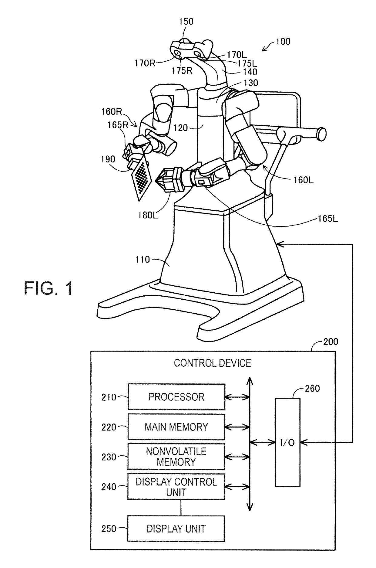
[0021]FIG. 1 is a conceptual diagram of a robot system that executes a calibration method of a first embodiment. The robot system includes a robot 100 and a control device 200. The robot 100 is an autonomous robot capable of performing work while autonomously determining the work by recognizing a work target with cameras 170L, 170R, 175L, 175R, 165R, and 165L and freely adjusting the force. The robot 100 can operate as a teaching playback robot that executes work in accordance with prepared teaching data.

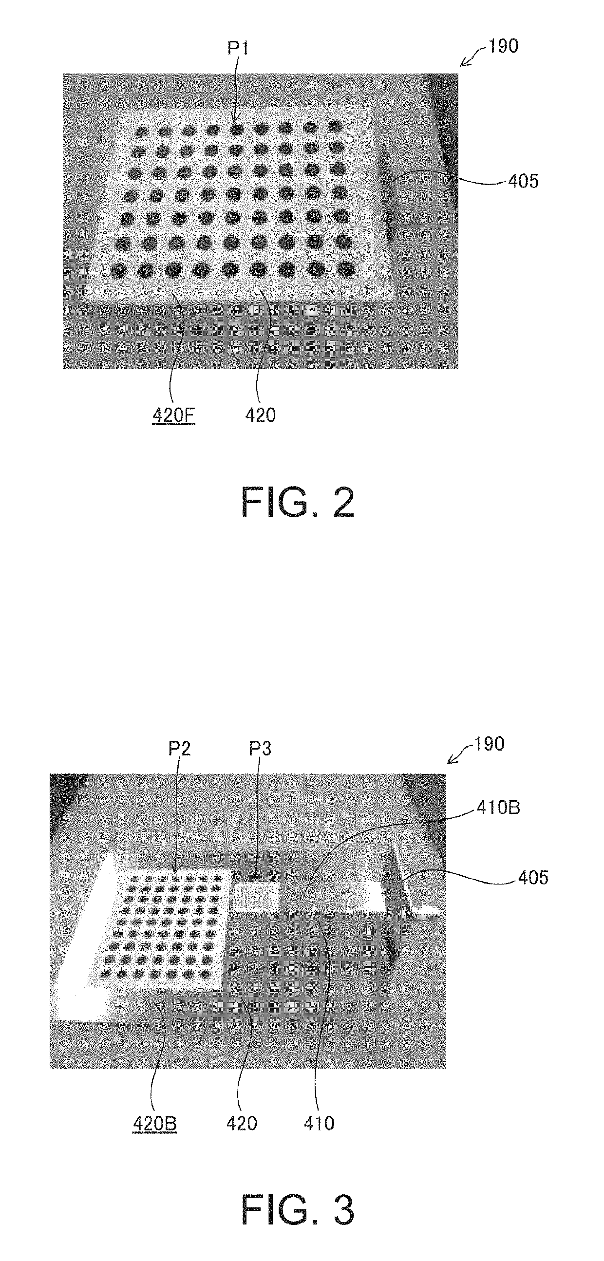
[0022]The robot 100 includes a base 110, a body portion 120, a shoulder portion 130, a neck portion 140, a head portion 150, and two arms 160L and 160R. A hand 180L and a calibration tool 190 are detachably attached to the arms 160L and 160R. A calibration tool 190 is a camera calibration tool provided with patterns P1, P2, and P3 to be described later. The hand 180L is an end effector that grips a workpiece or a tool.

[0023]Cameras 170L, 170R, 175L, and 175R are i...

second embodiment

B. Second Embodiment

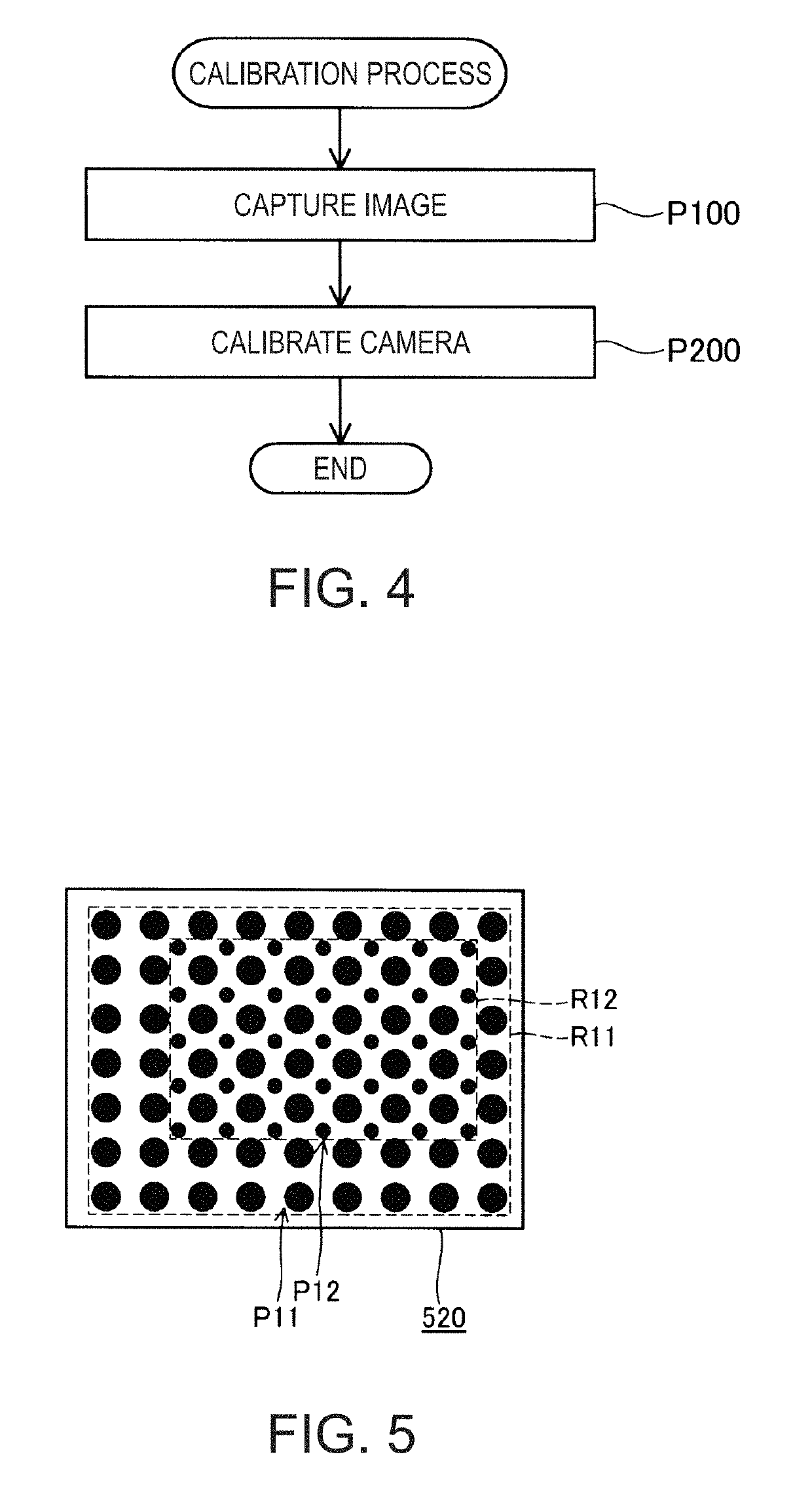
[0037]FIG. 5 is an explanatory view illustrating a surface 520 on which a pattern P11 and a pattern P12 are formed, of the calibration tool used in a calibration method of a second embodiment. In FIG. 5, the pattern P11 of the calibration tool is used for calibrating the camera 170 and the camera 175 of the robot 100 and a pattern P12 is used for calibrating the camera 165 of the robot 100.

[0038]The patterns P11 and P12 are circular shapes having the same mark shape and the sizes of the marks are different. The marks constituting the pattern P11 are larger than the marks constituting the pattern P12. The patterns P11 and P12 are formed on the same surface 520 of the surfaces constituting the calibration tool. A second rectangular region R12 circumscribing the pattern P12 is disposed inside a first rectangular region R11 circumscribing the pattern P11. In the second embodiment, the region R11 is disposed so as to encompass the region R12, but in another embodiment...


PUM


Abstract

A calibration method for calibrating a first camera and a second camera which are different in at least one of an angle of view and a focal length includes capturing images which include a calibration tool having a first pattern configured with a plurality of first marks and a second pattern configured with a plurality of second marks, different in at least one of a shape between the first mark and the second mark, a size between the first mark and the second mark, and arrangement between the first marks and the second marks, by the first camera and the second camera, and calibrating the first camera and the second camera using patterns corresponding respectively to the first camera and the second camera.

Description

BACKGROUND1. Technical Field[0001]The present invention relates to calibration of a plurality of cameras.2. Related Art[0002]In calibration of a camera, a calibration plate on which a calibration pattern is displayed may be used. In JP-T-2013-526423, a method of calibrating a plurality of cameras using the calibration plate is disclosed.[0003]However, in the related art, sufficient consideration has not been made on a case of calibrating the plurality of cameras in which at least one of an angle of view and a focal length is different. For that reason, in order to prepare a calibration pattern suitable for each camera, there is a problem that calibration work becomes complicated by replacing the calibration plate. For that reason, a technique that does not complicate calibration work for calibration of a plurality of cameras is demanded.SUMMARY[0004]An advantage of some aspects of the invention is to solve at least a part of the problems described above, and the invention can be imp...

Claims


Application Information

Patent Timeline
Patent Type & Authority Patents(United States)
IPC IPC(8): H04N7/18H04N13/246H04N5/247H04N13/239
CPCH04N5/247H04N13/239H04N13/246H04N17/002H04N23/90
Inventor NODA, TAKAHIKOINAZUMI, MITSUHIRO
Owner SEIKO EPSON CORP
Why Eureka
Try Eureka